Chapter 3: Wiring
Firmware – S1043
Revision: 2 (9/98)
22
© Saftronics, Inc.
3.2
Connection Diagram
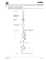
The connection diagram of the VG5 is shown in
Figure 3.2
.
When using the Digital Operator, the motor can be operated by wiring only the main circuits.
Figure 3.2
Connection Diagram (Model VG527P5 shown above)
VG5


