Chapter 3: Wiring
Firmware – S1043
Revision: 2 (9/98)
28
© Saftronics, Inc.
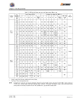
Table 3.3 Closed-Loop Connector Sizes (JIS C 2805) (For 200 V and 400 V Classes)
AWG Sizes
Wire Thickness mm
2
Terminal Screws
Size
M3.5
1.25-3.5
20
0.5
M4
1.25-4
M3.5
1.25-3.5
18
0.75
M4
1.25-4
M3.5
1.25-3.5
16
1.25
M4
1.25-4
M3.5
2-3.5
M4
2-4
M5
2-5
M6
2-6
14
M8
M8
2-8
M4
5.5-4
M5
5.5-5
M6
5.5-6
12-10
3.5/5.5
M8
5.5-8
M5
8-5
M6
8-6
8
8
M8
8-8
M6
14-6
6
14
M8
14-8
M6
22-6
4
22
M8
22-8
3-2
30/38
M8
38-8
M8
60-8
1-1/0
50/60
M10
60-10
3/0
80
80-10
4/0
100
M10
100-10
4/0
100
100-12
300MCM
150
150-12
400MCM
200
M12
200-12
M12 X 2
325-12
650MCM
325
M16
325-16
NOTE:
Determine the wire size for the main circuit so that line voltage drop is within 2% of the rated voltage. Line voltage
drop is calculated as follows (if there is the possibility or excessive voltage drop, use a larger wire suitable to the
required length.
Line voltage drop (V) =
/
3 x wire resistance (
Ω
/km) x wire length (m) x current (A) x 10
-3

