


NXP Semiconductors
UM11637
FRDMGD3160DCMHB evaluation board
5.2.2 Quick start
1. Download and install the latest FlexGUI software (see
)
2. Assemble the DCM
™
1000X SiC kit:
a. Assemble the three FRDMGD3160DCMHB boards together making sure that the
board edge connectors J25 and J26 are correctly plugged into each other. The
letters U, V, and W identify the boards according to
b. Plug the translator board and KL25Z assembly on board U.
c. Place the assembly on the evaluation kit, taking care to align the pins of the
power module to the corresponding sockets. The boards should click the plastic
standoffs once fully seated.
3. Check jumper configuration on the evaluation boards before powering up, and ensure
that the configuration meets desired use case; see
.
4. PWM signals must be provided on the three J13 (Ext PWM) connectors, referenced
to GND. Check the translator board J4 and J5 connectors to ensure that external
PWM control is used. PWMHSEL (J11) and PWMLSEL (J10) jumpers can be used
on each board to enforce or bypass deadtime control (see
).
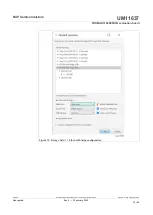
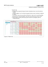
5. Launch FlexGUI application software on PC, and select the Daisy chain GD3160
(x6 – 1 channel) kit mode (see
). Connect USB cable from PC to USB
KL25Z port on KL25Z microcontroller board. KL25Z microcontroller is shipped with
proper firmware already flashed. See
for additional details.
6. Supply 12 V DC power (1 A current capability minimum) to the low-voltage domain
of FRDMGD3160DCMHB boards. Power one board through VSUP TP6 and GND
TP7, the other two boards are supplied by the first one. Check VCCL, VCCH, VEEL,
VEEH voltage levels regarding GNDH and GNDL test points on all three boards. If
VCC voltages are low, adjust their respective R65 potentiometer.
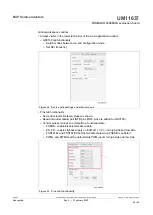
7. Start FlexGUI communications. All six GD3160 can now be configured, faults, and
ADC measurements collected.
Designator
Signal
Position
Definition
Translator board
J4
J5
PWMH_SEL
PWML_SEL
2-3
PWM control from MCU disabled, input from J13 (Ext PWM) on each
FRDMGD3160 board
FRDMGD3160DCMHB boards
J13
Ext PWM
-
input external PWM for each phase on this connector
J1
PS_EN
2-3
flyback power supplies always enabled (9.3 V UVLO)
R50
INTBL
INTBH
closed
FlexGUI displays the same information on INTBL and INTBH: LOW if
any of the six devices reports a fault
J21
MISO
open for boards U and V, closed for board W
J22
MOSI
open
for all boards
J23
CSB
2-3
for all boards
J24
MISO
2-3
for all boards
Table 8. Mandatory jumper positions for three-phase configuration
UM11637
All information provided in this document is subject to legal disclaimers.
© NXP B.V. 2022. All rights reserved.
User guide
Rev. 2 — 3 February 2022
21 / 42


