SOUTHERN AVIONICS COMPANY
Model SA100 Dual
4-1
Installation and Operation
4 Installation and Operation
For security and/or safety, it may be desirable to enclose the transmitter in a building, and/or to
enclose the transmitter and antenna site with a fence. A grounded metal building and a
grounded metal fence are preferred. If wood or some other absorbent material such as concrete
blocks or brick is used, it must be sealed so that it cannot absorb moisture. An absorbent
structure close to the antenna will cause the antenna resistance to increase when the structure
absorbs moisture. This will cause the antenna current to decrease and, in an extreme case, can
activate the automatic shutdown system.
4.1 Transmitter Installation
1 Check that the jumpers on the AC Power Supply are correct. See figures "AC Power Supply
Schematic" and AC Power Supply Diagram."
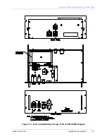
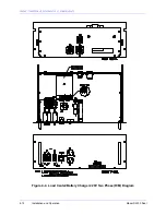
2. Complete the Load Center/Battery Charger installation. See section "Load Center/Batt
Charger Installation (Optional)."
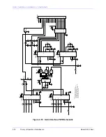
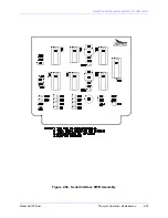
3. Check that the Filter PWB(s) jumpers are in the correct positions for the RF frequency, see
figures "Filter PWB Schematic, "Filter PWB Diagram," "Filter PWB Jumper Detail." Ensure
that the Filter PWB(s) are correctly installed on the RF Motherboard(s).
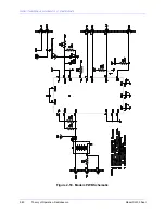
4. If the optional Audio PWB is installed, connect the balanced audio line input. See figure
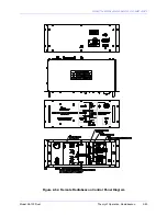
"Transmitter Diagram SA Series." See figure "SA Relay 24VDC PWB Diagram" for dual
units.
Danger
Potentially lethal levels of voltage are present within the
transmitter. Extremely high levels of RF voltage are present within the
coupler when RF input is applied. High levels of voltage can be deadly.
Summary of Contents for SA100
Page 20: ...SOUTHERN AVIONICS COMPANY Model SA100 Dual x Contents...
Page 22: ...SOUTHERN AVIONICS COMPANY Model SA100 Dual 1 2 Introduction This page intentionally left blank...
Page 25: ...SOUTHERN AVIONICS COMPANY Model SA100 Dual 1 5 Introduction Figure 1 2 Transmitter Portrait...
Page 26: ...SOUTHERN AVIONICS COMPANY Model SA100 Dual 1 6 Introduction This page intentionally left blank...
Page 28: ...SOUTHERN AVIONICS COMPANY Model SA100 Dual 1 8 Introduction This page intentionally left blank...
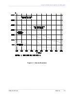
Page 119: ...SOUTHERN AVIONICS COMPANY Model SA100 Dual 3 3 Antennas Figure 3 1 Antenna Reactance...
Page 120: ...SOUTHERN AVIONICS COMPANY Model SA100 Dual 3 4 Antennas This page intentionally left blank...
Page 160: ...SOUTHERN AVIONICS COMPANY Model SA100 Dual 5 8 Maintenance This page intentionally left blank...
Page 162: ...SOUTHERN AVIONICS COMPANY Model SA100 Dual 6 2 Parts List This page intentionally left blank...
Page 164: ...SOUTHERN AVIONICS COMPANY Model SA100 Dual 6 4 Parts List This page intentionally left blank...
Page 218: ...SOUTHERN AVIONICS COMPANY Model SA100 Dual 6 58 Parts List This page intentionally left blank...

