SOUTHERN AVIONICS COMPANY
Model SA100 Dual
2-63
Theory of Operation, Radiobeacon
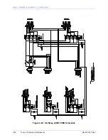
The Normal/Test switch applies power to the standby, or non-operating transmitter. When the
Normal/Test switch is placed in the Test position, power is applied to both power relays K2 and
K3. AC and DC power is thus applied to both upper and lower transmitter. The antenna relay K1
connections are cross- connected so that when one transmitter is attached to the RF output, the
other transmitter is attached to the Dummy Load. When K1 changes state, the connections are
reversed.
NOTE: An external 50 Ohm dummy load must be attached to the dummy load terminal before
the Normal/Test switch is placed in the Test position or damage may occur to the standby
transmitter. In the SA series this is accomplished by connecting 5A1A2TB4 pin 7 and 8 to
transmitter #1’s built in Dummy Load.
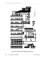
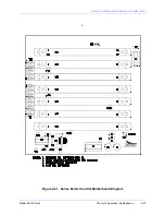
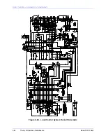
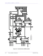
Logic signals for transmitter ON/OFF control, Primary Transmitter Select, and Reset to Primary
Transmitter are derived from the momentary acting control switches located on the Transfer
Indicator Board or, with remote control, from momentary pull-down signals generated on the
remote panel and exercised through the Serial Interface Board. When Transmitter Select Switch
S1 is momentarily pressed to the Transmitter 1 position, Pin 16 of K1 on the Local Control
Motherboard is momentarily grounded. This magnetically latches K1 with contacts between Pins
11 and 13 closed. This will ground Pin 10 of the Autotransfer Logic Board causing Transmitter 1
to be selected as primary. The contact between Pins 9 and 13 of K1 will be simultaneously
opened, causing the Transmitter 1 Primary Transmitter LED to be lit. When the Transmitter
Select Switch is pressed to the Transmitter 2 position, Pin 15 of K1 is grounded, causing K1 to be
magnetically latched with K1 contacts between Pins 13 and 9 closed and opened between Pins
13 and 11. This causes Transmitter 2 to be selected as primary and, through Q1, lights the
Transmitter 2 Primary Transmitter LED. Transmitter ON/OFF control is produced in a similar
manner with transmitter ON/OFF switch S2 magnetically latching Local Control Motherboard
relay K2 with relay contacts between pins 13 and 11 closed for transmitter OFF or contacts open
for transmitter ON.
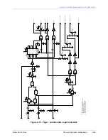
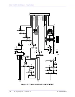
Pressing the Reset pushbutton grounds reset input Pin 11 of the Autotransfer Logic Board and
initiates a reset sequence.
Summary of Contents for SA100
Page 20: ...SOUTHERN AVIONICS COMPANY Model SA100 Dual x Contents...
Page 22: ...SOUTHERN AVIONICS COMPANY Model SA100 Dual 1 2 Introduction This page intentionally left blank...
Page 25: ...SOUTHERN AVIONICS COMPANY Model SA100 Dual 1 5 Introduction Figure 1 2 Transmitter Portrait...
Page 26: ...SOUTHERN AVIONICS COMPANY Model SA100 Dual 1 6 Introduction This page intentionally left blank...
Page 28: ...SOUTHERN AVIONICS COMPANY Model SA100 Dual 1 8 Introduction This page intentionally left blank...
Page 119: ...SOUTHERN AVIONICS COMPANY Model SA100 Dual 3 3 Antennas Figure 3 1 Antenna Reactance...
Page 120: ...SOUTHERN AVIONICS COMPANY Model SA100 Dual 3 4 Antennas This page intentionally left blank...
Page 160: ...SOUTHERN AVIONICS COMPANY Model SA100 Dual 5 8 Maintenance This page intentionally left blank...
Page 162: ...SOUTHERN AVIONICS COMPANY Model SA100 Dual 6 2 Parts List This page intentionally left blank...
Page 164: ...SOUTHERN AVIONICS COMPANY Model SA100 Dual 6 4 Parts List This page intentionally left blank...
Page 218: ...SOUTHERN AVIONICS COMPANY Model SA100 Dual 6 58 Parts List This page intentionally left blank...

