SOUTHERN AVIONICS COMPANY
Model SA100 Dual
2-11
Theory of Operation, Radiobeacon
2.3.3 Tone Key
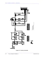
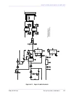
This board is used to generate the audio tone signal and DC level used on the Driver Modulator
(DMOD) board to control the modulation voltage. U1D and its circuitry generate either a 400 or
1020 Hz signal depending on the position of jumpers. U1A and its circuitry comprise a 1020 Hz
active filter and U1C and its circuitry comprise a 400 Hz active filter.
The selected tone frequency is fed to Gate U2A which is controlled by the squelch signal that will
be present when an external voice signal is used. With no external voice signals, no jumpers are
connected at pin 13 of U2 and pin 13 is held high at 12V turning the gate on. If a jumper
connects pin 13 to the squelch control line, a voice signal will cause the gate to turn off and the
audio tone will bypass the gate through R11 with a consequent decrease in amplitude. This
feature is used when simultaneous voice and code tone modulation is desired with a low level
code tone present whenever voice is present. When the voice signal is absent, the code tone will
revert back to its full amplitude. By connecting pin 13 of U2 to ground, the code tone amplitude
will remain at a low level irrespective of the voice signal. For non-voice use, neither jumper is
used and the code tone level is adjusted for full modulation percentage.
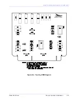
The code signal from Gate U2A is fed through Gate U2B which is controlled by the Keyer at pin
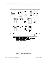
18. To select 1020 Hz or 400 Hz tone, install the appropriate jumpers that correspond with the
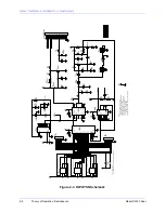
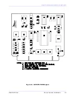
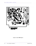
desired frequency. See figure "Tone Key PWB Schematic" and "Tone Key PWB Diagram."
Provisions are available for operating the transmitter in the optional emission modes of CW,
MCW, KMCW and PTT.
Summary of Contents for SA100
Page 20: ...SOUTHERN AVIONICS COMPANY Model SA100 Dual x Contents...
Page 22: ...SOUTHERN AVIONICS COMPANY Model SA100 Dual 1 2 Introduction This page intentionally left blank...
Page 25: ...SOUTHERN AVIONICS COMPANY Model SA100 Dual 1 5 Introduction Figure 1 2 Transmitter Portrait...
Page 26: ...SOUTHERN AVIONICS COMPANY Model SA100 Dual 1 6 Introduction This page intentionally left blank...
Page 28: ...SOUTHERN AVIONICS COMPANY Model SA100 Dual 1 8 Introduction This page intentionally left blank...
Page 119: ...SOUTHERN AVIONICS COMPANY Model SA100 Dual 3 3 Antennas Figure 3 1 Antenna Reactance...
Page 120: ...SOUTHERN AVIONICS COMPANY Model SA100 Dual 3 4 Antennas This page intentionally left blank...
Page 160: ...SOUTHERN AVIONICS COMPANY Model SA100 Dual 5 8 Maintenance This page intentionally left blank...
Page 162: ...SOUTHERN AVIONICS COMPANY Model SA100 Dual 6 2 Parts List This page intentionally left blank...
Page 164: ...SOUTHERN AVIONICS COMPANY Model SA100 Dual 6 4 Parts List This page intentionally left blank...
Page 218: ...SOUTHERN AVIONICS COMPANY Model SA100 Dual 6 58 Parts List This page intentionally left blank...

