SOUTHERN AVIONICS COMPANY
Model SA100 Dual
2-62
Theory of Operation, Radiobeacon
2.4 Detailed Circuit Analysis: Automatic Transfer
System SA Series
2.4.1 Local Radiobeacon Control System
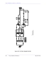
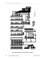
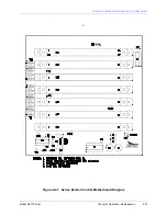
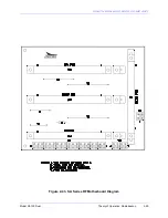
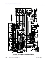
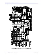
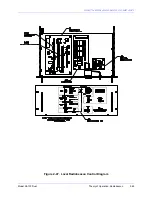
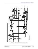
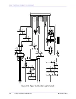
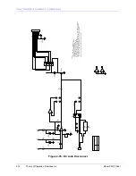
See Figures "Local Radiobeacon Control System Overall Schematic" and "Local Radiobeacon
Control System Diagram" for schematic and diagram drawings of the Local Radiobeacon Control
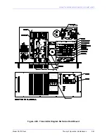
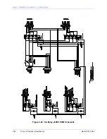
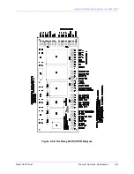
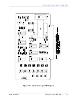
System, Figures "Autotransfer Logic PWB Schematic" and "Autotransfer Logic PWB Diagram"
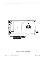
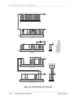
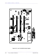
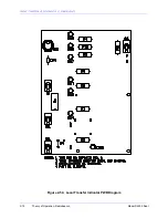
for schematic and diagram drawings of the Autotranfer Logic PWB, and Figure "Local Transfer
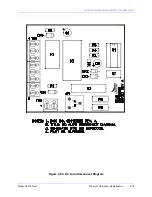
Indicator PWB Diagram" for the diagram drawing of the Local Transfer Indicator PWB.
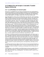
Upon initial application of power to the Local Radiobeacon Control System or after pressing the
RESET pushbutton on the Control panel, the system will begin a sequence to first remove power
from the secondary transmitter, then switch the antenna relay to the primary transmitter, and
finally apply power to the primary transmitter. This is accomplished through logic contained on
the Autotransfer Logic PWB. U2 pin 3 of the Autotransfer Logic PWB will initially begin with 0 V.
This will force a logic 1 (5V) on U3 pin 1. U3 generates a fixed delay in the passage of a logic
signal. After approximately 0.6 seconds, the logic signal which is present at U3 pin 1 will appear
at U3 pins 12, 13. After an additional 0.6 seconds, the logic signal will appear at pin 6 of U3. The
logic signals from pins 1, 12 and 6 of U3 pass to U4 gates C, B and D, respectively, where they
will be inverted if the upper transmitter is selected as primary, or passed through without
inversion if the lower transmitter is selected as primary. The logic signals from gates B and C are
applied to U7 to set and re-set the flip-flops formed by U7 gates A, B, C and D. These control the
relay drivers for K2 and K3, the upper (Transmitter 1) and lower (Transmitter 2) transmitter power
relays respectively. The output of U4 gate D is applied through an inverting buffer of U6 to Q3,
the relay driver for antenna relay K1. After the primary transmitter receives operating power it will
respond with a 12 V sense signal to indicate proper transmitter operation. This signal, present at
pin 12 or 13 of the Autotransfer Logic PWB, will be coupled through gates A, B and C of U1 to U2
pin 5. The sense signal for the SA series transmitters is approxi12 volts.
With a logic 1 now present at U2 pin 5, a logic 0 will be present at pins 3 and 4, and a logic 1 at
pin 2. The transfer unit will thus be latched into the primary transmitter mode. A failure within the
primary transmitter, signaled by a drop in the sense line voltage from 12 V to 0 V, will produce a
logic 0 at U2 pin 5, a logic 1 at pins 3 and 4, and a logic 0 at pin 2. As the logic 0 now present at
U3 pin 1 is passed through the two delays of U3, the transfer logic will first remove power from
the primary transmitter, then transfer antenna connections to the secondary transmitter. The
removal of power from the primary transmitter prevents a reapplication of the 12 V sense signal
and latches the transfer unit into the secondary mode. Logic gates in integrated circuits U2 and
U5 furnish indications of system status through the control panel Primary, Secondary and Fail
LED's.
The ON/OFF transmitter power switch is used to turn off or turn on the operating transmitter via
the Logic OFF/ON control signal applied to pin 18. The primary transmitter always comes on first
irrespective of whether the primary or secondary was working when the transmitter power was
turned OFF.
Fail Alarm relay K1 on the Autotransfer Logic PWB furnishes remote alarm capability through a 1
form C SPDT relay contact set. The relay is activated in primary or secondary mode, and
deactivated for fail mode or loss of operating power. The contacts are rated 1 amp at 115 VAC
with a resistive load.
Summary of Contents for SA100
Page 20: ...SOUTHERN AVIONICS COMPANY Model SA100 Dual x Contents...
Page 22: ...SOUTHERN AVIONICS COMPANY Model SA100 Dual 1 2 Introduction This page intentionally left blank...
Page 25: ...SOUTHERN AVIONICS COMPANY Model SA100 Dual 1 5 Introduction Figure 1 2 Transmitter Portrait...
Page 26: ...SOUTHERN AVIONICS COMPANY Model SA100 Dual 1 6 Introduction This page intentionally left blank...
Page 28: ...SOUTHERN AVIONICS COMPANY Model SA100 Dual 1 8 Introduction This page intentionally left blank...
Page 119: ...SOUTHERN AVIONICS COMPANY Model SA100 Dual 3 3 Antennas Figure 3 1 Antenna Reactance...
Page 120: ...SOUTHERN AVIONICS COMPANY Model SA100 Dual 3 4 Antennas This page intentionally left blank...
Page 160: ...SOUTHERN AVIONICS COMPANY Model SA100 Dual 5 8 Maintenance This page intentionally left blank...
Page 162: ...SOUTHERN AVIONICS COMPANY Model SA100 Dual 6 2 Parts List This page intentionally left blank...
Page 164: ...SOUTHERN AVIONICS COMPANY Model SA100 Dual 6 4 Parts List This page intentionally left blank...
Page 218: ...SOUTHERN AVIONICS COMPANY Model SA100 Dual 6 58 Parts List This page intentionally left blank...

