


19
0171-761-EN
12. Common condenser.
All compressors are coupled to a
common condenser.
0. No
1. Yes
13. Set points/current limit no.1/no.2
The digital input
set points no. 1/no.2
is used either to change between two
set points for suction pressure and
brine temperature (parameter 13 = 0),
or between two limit values for high
motor current (parameter 13 = 1).
14. Auxiliary outputs.
0. Warning
1. Cap. < limit
2. Cap. > limit.
15. Low warning limit for suction
pressure
This field indicates the interval be-
tween low alarm limit and low
warning limit for suction pressure in
°
C
sat
(0 - 10K).
16. Low warning limit for brine temp.
This field indicates the interval be-
tween low alarm limit and low warn-
ing limit for brine temperature in
°
C
(0 - 10K).
·
Current parameter value
This field shows the current value of the
selected parameter.
·
New parameter value
The first time you use this field it will
show the current value of the selected pa-
rameter. If the parameter can be changed,
do so here. Refer to the chapter
Changing parameters
for further infor-
mation.
·
Suction temperature calibration
·
Discharge temperature calibration
·
Oil temperature calibration
·
Brine temperature calibration
This field is used to calibrate the tempe-
rature measurements. Usually it is not
necessary to calibrate them. However, if
the wire connecting a transducer to
UNISAB S-Control is long, the stated
temperature will be too high, because the
resistance of the wire contributes to the
measured resistance value. The following
three methods can compensate for this:
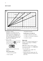
A By using the curve in figure 1, you
can read the contribution of the cable
in
°
C. Enter this value as calibration
value for the measurement concerned.
B Measure the temperature where the
sensor is placed by means of a mea-
suring gauge. At the same time you
can read the temperature of the mea-
suring point concerned in the
co-
lumn in the display. The difference be-
tween the two measuring values
should be entered as calibration value,
after which the two measuring values
must be identical.
C Immerse the sensor in
ice water
(pure
water with crushed ice, no salt!) or re-
place it by a precision resistor of 100
W (
a deviation of 0.4
W
corresponds
to 1
°
C)
.
Press the
SET
key while one
of the LEDs in the
column is lit, in
order to adjust the measurement to
0
°
C.
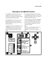
Summary of Contents for UNISAB S-Control
Page 1: ......


