


9
0171-761-EN
The keyboard must be used to move the sig-
nal to another LED -- please refer to pos. 4
Keyboard
.
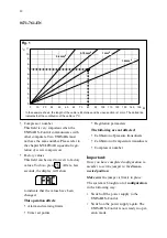
The values should be interpreted as follows:
SUCTION PRESSURE
is the pressure of
the refrigerant on the suction side of the
compressor, displayed relative to atmosphe-
ric pressure.
The LED in brackets indicates the
set point
(SP).
DISCHARGE PRESSURE
is the pressure
of the refrigerant at the pressure side of the
compressor, displayed relative to atmosphe-
ric pressure.
DIFF. PRESSURE is
the pressure differ-
ence between the oil pressure in the flow
switch chamber and the suction pressure.
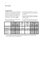
Low alarm limit indicates the values at
which an alarm occurs. High alarm limit is
for setting of the oil filter differential pres-
sure over the oil filter. The actual reading of
oil filter differential pressure is not available
on the display.
NB
The measured oil filter differential pressure
also includes the pressure drop through the
oil cooler the and pipe system. With warm
oil this drop will be approx. 0.5 bar, in addi-
tion to the pressure drop in the oil filter, and
with cold oil somewhat more.
TIMER NO./ TIME/ SP
(please refer to the chapter
Timers
)
0:
Hour counter (hours x 10 = number of
operating hours)
1:
Start/start
2:
Stop/start
3:
Prelubrication
4:
Oil flow
5:
Motor feedback
6:
Suction pressure ramp function
7:
Slide max.
8:
Delay before start
9:
Delay before stop
Digital inputs
:
10: Motor feedback
11: External start permission (normal
stop)
12: External start permission (instant stop)
13: Set points no. 1/no. 2
14: Oil flow switch
15: Thermistor
SUPERHEAT
is the temperature difference
between suction gas temperature before the
compressor (
°
C) and pressure (
°
C
sat
).
DISCHARGE TEMPERATURE
is the
discharge gas temperature as the gas leaves
the compressor.
OIL TEMPERATURE
is the temperature
of the oil at the oil flow switch.
BRINE TEMPERATURE
can be used to
alter the capacity regulation so that this
function is controlled by the brine tempera-
ture, and not by the suction pressure.
The LED in brackets indicates the
set point
(SP).
MOTOR CURRENT
shows the power
consumption of the motor expressed in am-
pere. The measuring zone must be set cor-
rectly. Please refer to the chapter
Measuring
the Motor Current.
CAPACITY SLIDE POSITION
is the po-
sition of the capacity slide shown as a per-
centage.
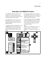
Summary of Contents for UNISAB S-Control
Page 1: ......


