TRANSMISSION SETUP
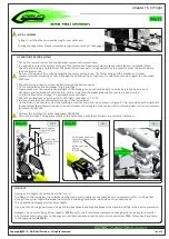
It is important to choose the right reduction ratio to maximize efficiency based on your required flight performance.
The Goblin has many possible reduction ratios at your disposal. It is possible to optimize any motor and battery combination.
It is recommended to use wiring and connectors appropriate for the currents generated in a helicopter of this class.
If you are using a head speed calculator which requires a main gear and pinion tooth count, use
214
teeth for the main gear
(this takes into account the two stage reduction) and the tooth count of your pulley as the pinion count.
Below is a list of available reduction ratios
:
H0015-18-S - 18T Pinion = ratio 11.9:1 H0015-22-S - 22T Pinion = ratio 9.7:1
H0015-19-S - 19T Pinion = ratio 11.3:1 H0015-23-S - 23T Pinion = ratio 9.3:1
H0015-20-S - 20T Pinion = ratio 10.7:1 H0015-24-S - 24T Pinion = ratio 8.9:1
H0015-21-S - 21T Pinion = ratio 10.2:1 H0015-26-S - 26T Pinion = ratio 8.2:1
H0015-xx-S is a motor pulley for 6mm motor shaft.
Avaible H0126-xx-S motor pulley for 8mm motor shaft.
Note: Although the Goblin can fly at high rpm, for safety reasons we suggest to not exceed 2350 rpm.
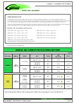
Some example configurations:
GOBLIN 630 COMPETITION CONFIGURATIONS
Rev:01
Performace
Battery
Motor
ESC
Pinion
RPM
Max (Gov)
Pitch
GENERAL
10S
4000/4500
Pyro 700-56
Edge 120 HV (V2)
24T
2100
± 12,5
Jive 120 HV
YGE 120 HV
23T
2100
± 12,5
Scorpion
4025-730
Edge 120 HV (V2)
19T
2100
± 12,5
Jive 120 HV
YGE 120 HV
18T
2100
± 12,5
12S
3700/4000
Quantum
4135-560
Scorpion
4035-560
Pyro 700-56
Edge 120 HV (V2)
23T
2300
± 12,5
Jive 120 HV
YGE 120 HV
21T
2300
± 12,5
Scorpion
4225-610
Jive 120 HV
YGE 160 HV
20T
2400
± 12,5
Copyright@2013 - SAB Heli Division - All rights reserved
Page 21
Chapter 11, Installation Of The Motor


