12
INSTALLATION—ELECTRICAL WIRING ROUTING
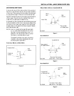
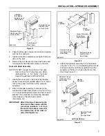
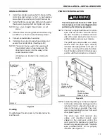
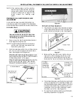
Figure 27
IMPORTANT: To prevent the eyes on the front
side of the door from interfering
with the eyes on the back of the
door, the emitter modules must
be installed diagonally from
each other. The same is true for
the receiver modules.
1.
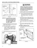
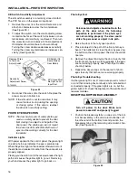
After the mounting brackets are in place, install the
emitter module in the left bracket and the receiver
module in the right bracket.
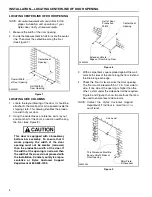
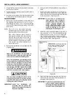
NOTE: The receiver module can be identified by
the two small lights, one yellow and one
green. The emitter module has only a
green light. The yellow alignment light will
be lit when the photo eyes are aligned.
(See Figure 28)
Figure 28
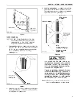
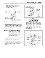
Position the large, plastic nuts found on
the end of each photo eye so that the lens
on either eye does not protrude too far
past the edge of the mounting bracket. If a
lens sticks out too far, that photo eye will
be susceptible to damage.
2.
Thread the connector found on the terminated end
of each wire cable onto the end of the photo eyes.
NOTE: Be sure the path through which the wire
cables are routed hides and protects them
from damage. If necessary, run conduit to
each mounting bracket to protect the
cables.
3.
Route the wire cables from the photo eyes to the
control panel in a manner conforming to all applica-
ble codes and regulations. Shielded cable is recom-
mended for all photo eye wires.
4.
Connect the photo eyes to the control panel as
shown on the schematic that was shipped with the
door.
5.
After all work is complete, clean the lens of each
photo eye using window cleaner and a soft, clean
cloth.
ELECTRICAL WIRING ROUTING
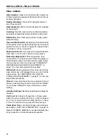
1.
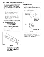
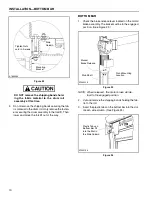
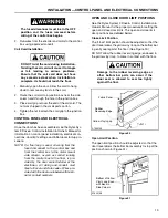
Locate the Rytec control box and fused disconnect.
(See Figure 29.)
Figure 29
Anchor
Locate
Hardware
A750119
Photo Eyes
12–36-in. O
Floor
Mount Bracket
Adjacent to Side
Column
Left Side of Door — Right Side Is a Mirror Image
A6500173
Power Light
(Green)
Alignment Light
(Yellow)
Emitter Module
NOTE: Photo eyes are joined for photo purposes.
Receiver
Module
A7500253
Fused Disconnect
(Supplied by Door
Owner)
Conduit to Floor Loop
(If Required) Supplied
by Door Owner
4 ft.
Rytec
System 3
Control
Panel
Summary of Contents for Pharma-Roll
Page 1: ...Pharma Roll Installation Manual Revision January 15 2009 0715009 Rytec Corporation 2007...
Page 2: ......
Page 23: ...NOTES 19...
Page 24: ......

