Page 10
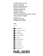
Fig. 8
TRIGGER SWITCH
LOCK-ON
BUTTON
5
°
TO 15
°
OPERATION
workpiece. Start your grinder and let the motor and grinding
wheel build up to full speed. Gradually lower grinder until the
grinding wheel contacts the workpiece.
For best results keep the grinder tilted at an angle from 5 to
15 degrees and continuously moving at a steady, consistent
pace. Move the grinder back and forth or up and down over
the work area. Keep the grinder moving so that an excessive
amount of material is not removed from one area. If the
grinder is held in one spot too long, it will gouge and cut
grooves in the workpiece. If the grinder is held at too sharp
an angle, it will also gouge the workpiece because of
concentration of pressure on a small area.
Use just enough pressure to keep the grinder from chattering
or bouncing. Heavy pressure will decrease its speed and put
a strain on the motor. Normally the weight of the tool alone
is adequate for most grinding jobs. Use light pressure when
grinding jagged edges or loose bolts where there is the
potential for the grinder to snag on the metal edge.
Lift the grinder away from the workpiece before turning your
grinder off.
CAUTION:
Never cover air vents. They must always be open for
proper motor cooling.
SWITCH
See Figure 7.
To turn your grinder ON, depress the switch trigger. Release
the switch trigger to turn your grinder OFF.
LOCK-ON FEATURE
See Figure 7.
Your grinder has a lock-on feature that is convenient when
continuous operation for extended periods of time is required.
To lock-on, depress the trigger switch, push in the lock button
located on the side of the handle, then while holding the lock
button pushed in, release the trigger. To release the lock,
depress the trigger switch and release it.
GRINDING
See Figure 8.
Always carefully select and use grinding wheels that are
recommended for the material to be ground. Make sure that
the minimum operating speed of the grinding wheel selected
is not less than 11,000 rpm. The grinding wheel provided with
your grinder is suitable for grinding welds, preparing sur-
faces to be welded, grinding structural steel, and grinding
stainless steel.
Secure all work before beginning a grinding operation.
Secure small workpieces in a vise or clamp to a workbench.
DANGER:
Never use your grinder with the guard removed. It has
been designed for use only with the guard installed.
Attempting to use grinder with guard removed will result
in loose particles being thrown against the operator
resulting in serious personal injury.
WARNING:
Never use your grinder without wearing eye protection.
Following this rule will reduce the risk of serious personal
injury.
The key to efficient operation begins by controlling the
pressure and surface contact between the grinding wheel
and workpiece. Flat surfaces are ground at an acute angle,
normally between 5 to 15 degrees.
For maximum control, hold the grinder in front and away from
you with both hands, keeping the grinding wheel clear of the
Fig.
7