


Page 11
WARNING:
When servicing use only identical Ryobi replacement parts. Use of any other parts may create a hazard or cause product
damage.
MAINTENANCE
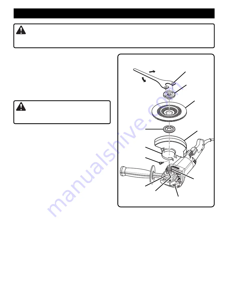
WRENCH
CLAMP
NUT
GRINDING
WHEEL
GUARD
DISC
FLANGE
CLAMP
SCREW
TO
LOOSEN
TO
TIGHTEN
CLAMP
FLAT(S)
SPINDLE
LOCK BUTTON
SPINDLE
BEARING CAP
Fig. 9
GUARD REPLACEMENT
See Figure 9.
After extended use, the guard may become worn and need
adjustments or replacing. If you drop your grinder and
damage the guard it may also be necessary for you to
replace it.
PROCEED AS FOLLOWS WHEN REPLACEMENT IS
REQUIRED:
■
UNPLUG YOUR GRINDER.
WARNING:
Failure to unplug your grinder could result in accidental
starting causing serious injury.
■
Remove and reassemble parts as shown in figure 9.
■
Depress spindle lock button and rotate clamp nut until
spindle locks.
■
Using the wrench provided, loosen and remove clamp
nut from spindle.
■
Remove grinding wheel and disc flange.
■
Using a screwdriver, loosen the clamp screw until the
guard can be adjusted or removed.
■
If you are making adjustments, rotate the guard to its
correct position as shown in figures 4, 5, and 9, then
retighten clamp screw securely
. Never use your grinder
without the guard in place and properly adjusted.
See Figures 4 and 5.
■
If you are replacing the guard, loosen the clamp screw
until the guard and clamp can be removed from the
bearing cap.
■
Place the new guard and clamp on the shoulder of the
bearing cap.
See Figure 9.
NOTE: If the new guard and clamp will not fit, loosen the
clamp screw until they slide over the bearing cap.
■
Rotate guard to the correct position as shown in figure 9.
■
Tighten clamp screw securely.
■
Reassemble disc flange, grinding wheel, and clamp nut.
Refer to "INSTALLING THE GRINDING WHEEL" in-
structions on page 8.
■
Securely tighten the clamp nut with the wrench pro-
vided.


