background image

2015-2017 5.0L Mustang Phase 1-2 RHD ROUSHcharger Kit
SECTION B – MODIFICATIONS

1316-RHD-AA 12152016  

33


800.59.ROUSH

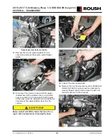
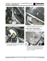
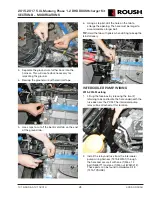
4.  Insert the clip (20860) found in Hardware Kit H 

(1315-TVSHKH) onto the tab on the bottom of the 
intercooler degas bottle (1315-8D080).

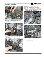
5.  Position the intercooler degas bottle to the fan 

shroud and check the fi t, but do not install. 
Remove additional material as required so the 
bottle fi ts properly.

FRONT COVER MODIFICATION

Wear safe eye protection when grinding to prevent 
serious personal injury. 

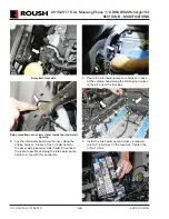
1.  If not already done so, clean the engine surfaces 

with brake clean and dry with shop air.

2.  Block off the grinding area to prevent debris and 

metal shavings from spreading through the engine 
compartment.

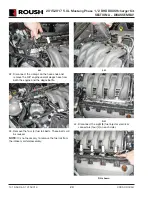
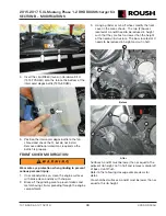
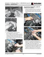
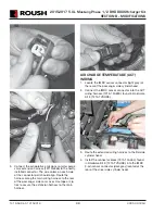
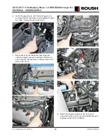
3.  Using a grinder or cut-off wheel, modify the front 

cover in the areas shown.  The two (2) bosses 
located at A and B need to be reduced in height 
such that they are fl ush, or lower than the height 
of the nearby rib structure.  The boss located at C 
needs to be reduced in height and cut in half.

A

B

C

Before

A

B

C

After

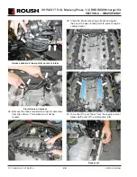
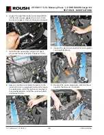
Surfaces A and B must be lower than or equal to the 
adjacent rib height. Cut in half and remove material off 
of boss C until fl ush.

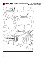
Refer to the following closeup example views for 
detail.

Crosshatched surfaces A and B must be lower than or 
equal to this rib height.

Summary of Contents for 1316-RHD-AA

Page 1: ...2015 2017 5 0L Mustang Phase 1 2 Right Hand Drive ROUSHcharger Kit Installation Instructions P N 422011 1316 RHD AA 39555 Schoolcraft Rd Plymouth MI 48170 800 59 ROUSH...

Page 2: ...questions please contact ROUSH Performance at 1 800 59 ROUSH Premium fuel 91 octane or higher is required to prevent spark knock or detonation under certain operating conditions The use of fuel additi...

Page 3: ...ing 36 Evaporative Emissions Canister Purge Valve Wiring 37 Air Charge Temperature ACT Wiring 38 TPS ETC and EECPV Harness Routing 39 Engine Harness Ground Wire 40 Intercooler Pump Wiring 41 Knock Sen...

Page 4: ...K85 1 Fastener Pulley to Supercharger M6 x 1 0 x 16 W500013 6 Fuel Injector Kit 13119F593K 1 Fuel Rail Assembly 1315 19F792 1 Clip Fuel Injector 13119C995 8 T Body Spacer 1315 9P697 1 T Body Assembly...

Page 5: ...18K579 1 Vacuum Harness Supercharger Bypass Reference 7R3V 9E498 1 Wiring Hardware Kit E Wiring 1315 TVSHKE 1 Electrical Jumper I C Pump 1315 8W501 1 ACT Wiring Harness 1315 12A690 1 TPS ETC Extensio...

Page 6: ...Degas bottle to Fan shroud and I C Pump Brkt M6 x 1 00 x 16 N605891 3 Nut LTR to Rad Support M8 W520413 4 Bolt LTR Bracket to Chassis N804394 S439 W705128 6 J Clip M8 Short W520823 2 Degas Bottle to...

Page 7: ...tchet or Breaker Bar Short Phillips head Screwdriver 5 8 Fuel Line Removal Tool Solder and Soldering Iron Heat Gun or Small Torch for Heat Shrink Tubing Tie Straps Zip Ties Trim Pad Tool for pushpin r...

Page 8: ...g and is subject to change without notice or liability Roush Performance Products reserves the right to revise the information presented herein or to discontinue the production of parts described at a...

Page 9: ...personal injury Do not smoke or carry lighted tobacco or open ame of any type when working on or near any fuel related components Highly ammable mixtures are always present and can be ignited resulti...

Page 10: ...8 mm head bolts 8 Release the eight 8 pushpin retainers by pulling the center pin and remove the radiator trim cover S T O P STOP Before continuing refer to the CALKIT found on our website under prod...

Page 11: ...elivery Operating your engine without our calibration will result in engine damage or failure and will void all warranty NOTE It is important to reinstall the PCM in the vehicle it came from to preven...

Page 12: ...mended lifting points and place onto safety stands With the tires lifted off of the ground remove the front wheels 13 Note the position of the fourteen 14 small medium and large pushpins on the inner...

Page 13: ...in pan or bottle Use a 3 4 wrench to open petcock and allow coolant to drain out of the fitting 16 If equipped remove the four 4 nuts and the strut tower cross brace 15 mm socket The strut tower cross...

Page 14: ...e K brace Slide the K brace out from the cowl trim panel and remove it from the vehicle 19 Remove the eight 8 bolts holding the HVAC battery closeout 20 Remove the HVAC battery closeout 21 Pry up the...

Page 15: ...e vacuum line from the air cleaner tube 24 Disconnect the positive crankcase ventilation PCV tube from the clean air tube 25 Disconnect the PCV fresh air inlet tube from the left hand cam cover and re...

Page 16: ...ow MAF sensor connector by pulling the red locking tab back and pressing the black release tab Release the two 2 locking tabs securing the upper airbox lid to the lower airbox Disconnect the MAF wirin...

Page 17: ...ess the black release tab to disengage the lock 31 Unlock the green connector and disconnect the evaporative emission canister purge valve EECPV tube and electrical connector green Remove the EECPV tu...

Page 18: ...ROUSHcharger Kit SECTION A DISASSEMBLY 1316 RHD AA 12152016 17 800 59 ROUSH EECPV electrical connector EECPV tube quick connector with green lock Remove retainer on cam cover Remove tube from retainer...

Page 19: ...nection Use a cap tape or other suitable method to block the rail opening from contaminants 34 Disconnect the brake booster vacuum hose from the intake manifold This port is located directly behind th...

Page 20: ...CTION B HOSE 5 HOSE 3 39 Remove the LH heater hose support bracket and fuel rail cover from the LH side of the cylinder head 40 Remove the two 2 nuts and support bracket that retained the RH heater ho...

Page 21: ...the hose ends and remove the 3 8 engine coolant degas hose from both the engine and the degas bottle 43 Remove the four 4 fuel rail bolts These bolts will be reused NOTE It is not necessary to remove...

Page 22: ...ad 46 Remove the six 6 intake manifold mounting bolts 47 Lift the intake manifold and fuel rail assembly straight up and pull it forward to access the harness connectors at the rear Disconnect the CMC...

Page 23: ...of intake Pin retainers on harness 48 Remove the intake manifold and fuel rail assembly from the vehicle This hardware will not be reused 49 Clean the intake mounting surfaces and apply tape over the...

Page 24: ...r hose at the radiator Use a rag to catch excess coolant On the thermostat housing end of the hose push the clip down on the connector and remove the upper radiator hose from the vehicle Some coolant...

Page 25: ...12152016 24 800 59 ROUSH 55 Disconnect the electric fan harness connector on the cooling module Remove the two 2 bolts 10 mm socket securing the shroud to the cooling module then remove the electric f...

Page 26: ...the water pump pulley 57 Cut and remove the A C compressor belt Discard belt NOTE Make sure to remove coolant to keep components clean as you continue procedures 58 Unclip the engine electrical harnes...

Page 27: ...0 59 ROUSH 60 Remove the two 2 bolts from the thermostat housing 8 mm socket 61 Remove the thermostat housing assembly and set it aside 62 Remove the four 4 water pump mounting bolts 10 mm socket and...

Page 28: ...A 12152016 27 800 59 ROUSH 64 Cap or tape off the PCV port heater feed tube and the heater core ports on the firewall 65 Tape off the radiator hose port and inlet port 66 Tape off and block the thermo...

Page 29: ...mbly and lay it out on the bench as shown in the following steps SECTION A HOSE 1 HOSE 2 HOSE 4 SECTION B HOSE 5 HOSE 3 3 Release the clamp and remove Section A hose 1 from the brake booster hose and...

Page 30: ...irator to brake booster line 1315 9D690RHD into the black port on the brake aspirator assembly Then install the check valve that plugs into the brake booster 10 Install the line that goes from the sup...

Page 31: ...eeve 1150 18K579SLV found in Hardware Kit D 1315 TVSHKD over the length of the hose 1315 9G272 3 Install one 1 clamp 7329K11 found in Hardware Kit D 1315 TVSHKD onto each end of the new line Install t...

Page 32: ...e brace was cut Exposed point on modi ed K brace shown installed 4 Paint the cut area with Motorcraft High Temperature Anti Corrosion Coating to prevent corrosion 5 Cut the cross brace blue and cowl s...

Page 33: ...IFICATION 1 Place the IC degas bottle template 1315 DGSTMPL on the top of the fan shroud and align it with the shroud features Use a spring loaded punch or other suitable tool to mark the fan shroud f...

Page 34: ...ngine surfaces with brake clean and dry with shop air 2 Block off the grinding area to prevent debris and metal shavings from spreading through the engine compartment 3 Using a grinder or cut off whee...

Page 35: ...2015 2017 5 0L Mustang Phase 1 2 RHD ROUSHcharger Kit SECTION B MODIFICATIONS 1316 RHD AA 12152016 34 800 59 ROUSH A B 20 MM REMOVE MATERIAL OFF OF BOSS C UNTIL THE 20 MM HEIGHT IS ACHIEVED...

Page 36: ...he part Use caution as to not contact the cam covers 6 Deburr any rough edges on the cover and remove the retention harness from the wire harness INTAKE VALLEY MODIFICATION 1 Mark the boss in the inta...

Page 37: ...osition 1 the blue with green wire is in position 2 the brown wire is in position 3 the blue with orange wire is in position 4 the yellow wire is in position 5 and the green with violet wire is in pos...

Page 38: ...ALVE WIRING 1 Locate the evaporative emissions canister purge valve electrical connector 2 wire at the front of the passenger side cylinder head Use a proper de pinning tool to remove the connector fr...

Page 39: ...side cam cover Use tape or zip ties to secure the extension harness to the main harness AIR CHARGE TEMPERATURE ACT WIRING 1 Locate the IMRC sensor connector light grey at the rear of the passenger si...

Page 40: ...it SECTION B MODIFICATIONS 1316 RHD AA 12152016 39 800 59 ROUSH TPS ETC AND EECPV HARNESS ROUTING 1 Remove the wiring retainer and clip on the engine harness 2 Route both extension harnesses along the...

Page 41: ...ip ties 4 Wrap electrical tape around the two 2 blue CMCV connectors at the rear of the cylinder head as shown CMCV connectors taped up ENGINE HARNESS GROUND WIRE 1 Pry up the engine harness retainers...

Page 42: ...to enlarge the opening The hole must be larger to accommodate a larger bolt TIP Hold the tab with pliers when drilling to keep the tab stationary INTERCOOLER PUMP WIRING 2015 2016 Mustang 1 Lift up t...

Page 43: ...ess along the engine harness in back of the cylinder head to the driver side inboard cylinder head Disconnect the radio capacitor and plug the intercooler pump harness in line with this connector 4 Ro...

Page 44: ...near the RH strut tower and retighten the bolt to 10 Nm Coil up the extra wire slack 7 Route and tuck the intercooler pump harness under the engine harness and down the RH coil cover towards the fuse...

Page 45: ...stang 1 Install the relay and fuse from the intercooler pump wiring harness 1315 8W501 to each stud protruding from the battery box Put the relay on the upper stud and the fuse on the lower stud as sh...

Page 46: ...stall the ground wire with the existing ground wire near the RH strut tower and retighten the bolt to 10 Nm coil up extra wire slack 8 Route and tuck the intercooler pump harness under the engine harn...

Page 47: ...to the wiring convolute 2 Loosen the two 2 bolts which retain the knock sensors to the engine block 10 mm socket If necessary one 1 of the bolts and sensors can be removed for this modification proce...

Page 48: ...Disconnect the electrical connectors for each ignition coil eight 8 places 3 Remove the eight 8 fasteners holding the coil on plug assemblies in place 8 mm socket Save the fasteners for re use 4 Remo...

Page 49: ...park plugs using a 5 8 spark plug socket and 6 extension Torque to 14 Nm 8 Apply a small amount of dielectric grease to the inside of the coil on plug boots before attaching to the spark plugs Install...

Page 50: ...D BUILDUP 1 Remove the PCV purge hose 13116K817 from the packaging Release the clamp and separate the rubber section of hose as shown 2 Attach the rubber hose section from the PCV purge hose to the bu...

Page 51: ...charger and secure it with the clamp This is hose 1 created from the brake boost vacuum and aspirator assembly modification process 5 Connect the supercharger bypass reference vacuum line 7R3V 9E498 t...

Page 52: ...15 19F792 NOTE Verify that the anti rotation clips are properly aligned and fully engaged into the fuel rail injector cups AIRBOX ASSEMBLY 1 Insert the dirty air duct 1315 9F763 and install it into th...

Page 53: ...tray from the inside 4 Align the holes on the MAF tube assembly with the J clips on the airbox tray Install two 2 bolts W500224 M8 X 25 from Hardware Kit A 1315 TVSHKA and torque to 10 Nm 10 mm socket...

Page 54: ...tened 8 Install the upper airbox cover 1315 9643 on the airbox tray Using a T 30 Torx head bit install six 6 bolts W506976 from Hardware Kit A 1315 TVSHKA 9 Remove the grommets and sleeves from the fa...

Page 55: ...If the ROUSH boost gauge kit is going to be installed onto the vehicle the above grommet can be left out as the boost gauge kit has a pre installed grommet on the vacuum line that will go in this loc...

Page 56: ...manifold GROUND WIRE UNDER 5 WIRING RETAINERS HERE 5 1 3 4 2 6 5 Check that the hose in back of the intake manifold is routed around the electrical harness and towards the RH cam cover 6 Connect the A...

Page 57: ...ace the supercharger assembly 1315 6F066 on top of the intake manifold Ensure that the supercharger is fully seated on the intake mounting dowels Remove protective shipping covers 10 Install the ten 1...

Page 58: ...hose assembly Connect the hose with 1 2 barbed fitting from the supercharger to the 1 2 brake line and secure it with the attached clamp 13 Connect the check valve on the brake vacuum and aspirator a...

Page 59: ...Hardware Kit B 1315 TVSHKB Torque the fasteners to 10 Nm 18 Connect the fuel supply line to the fuel rail and lock it into position 19 Install the throttle body assembly R07060150 on the throttle body...

Page 60: ...back of the supercharger 22 Install the evaporative emission canister purge valve line to the body line tube below the brake booster Route the rest of the line behind the cylinder head to the RH rear...

Page 61: ...ener on the intercooler coolant inlet Torque the inter cooler tube bolt to 10 Nm 26 Route the hose along the RH fuel rail and down to the heater outlet at the firewall 27 Modify the firewall end of th...

Page 62: ...the heater inlet hose to the new heater outlet hose assembly with zip ties 31 Install the end of the PCV purge hose 13116K817 from the hose section previously disassembled onto the bottom rear fittin...

Page 63: ...water pump gasket 3 Install the water pump on the front cover and install the three 3 bolts only Leave out the bolt at the 10 o clock position Torque the bolts to 25 Nm 4 Install the thermostat housi...

Page 64: ...M8x1 25x60 bolts 11127083 and two 2 M8x1 25x84 bolts W704752 from Hardware Kit C 1315 TVSHKC Torque bolts to 25 Nm 7 Install two 2 idler pulleys 953045 onto the machined posts of the upper FEAD brack...

Page 65: ...t into the casting prior to positioning in vehicle in order to clear the sway bar 10 Install one 1 M8 x 1 25 x 41 mm bolt W705128 found in Hardware Kit C 1315 TVSHKC to fasten the tensioner bracket to...

Page 66: ...ck FEAD belt by rotating the tensioner counter clockwise and routing the belt as per the stock Ford belt routing INTERCOOLER LOW TEMPERATURE RADIATOR LTR ASSEMBLY 1 Raise the vehicle 2 If you have a p...

Page 67: ...on the right hand side and the Support Bracket 1315 8K244 on the left hand side Secure each bracket at the radiator using a bolt W705128 and Nut W520413 Secure each bracket to the chassis using a bol...

Page 68: ...asses through the close out panel without being kinked 8 Once a proper fit is obtained ensure the close out panel is secure in place 9 Install the LTR outlet hose through the close out panel to the in...

Page 69: ...ove the intercooler pump bracket NOTE The bracket is placed on the outside of the frame behind the wiper pump reservoir bracket to make it easy to drill the holes When installed the intercooler pump a...

Page 70: ...th the pump in board to the vehicle Install two 2 bolts W500224 M8 x 25 into the weld nuts Torque to 25 Nm 5 Install the intercooler pump outlet hose 1315 8K236 from the pump outlet over the side of t...

Page 71: ...7 Connect the intercooler pump harness electrical connecter to the intercooler pump and secure it with a zip tie to the bracket 8 Collect the excess intercooler pump harness and secure it with zip ti...

Page 72: ...ttle 1315 8D080 4 Install the intercooler pump inlet hose 1315 8D029 to the bottom of the intercooler degas bottle and secure it with the clamp CT19X12 Intercooler pump inlet hose 1315 8D029 5 Install...

Page 73: ...ll the intercooler degas bottle inlet hose 1315 8D031 to the outlet on the intercooler INTERCOOLER OUTLET CONNECTION Outlet hose connection at top port of intercooler 9 Install the hose to the interco...

Page 74: ...f the bottle and to the upper LH radiator Secure both ends of the hose with the clamps 5 Transfer the hose clamp from the bottle end of the factory degas hose to new 3 8 engine degas hose 1315 8276 In...

Page 75: ...UCTION SYSTEM 1 Remove the old MAF wire harness clip christmas tree that retained the harness to the body 2 Install the dirty air duct 1315 9F763 at the LH side of the radiator 3 Lower the airbox asse...

Page 76: ...ps R07130015 from Hardware Kit A 1315 TVSHKA Torque clamps to 3 Nm 6 Install the PCV fresh air inlet tube 1315 6758 by connecting the 90 degree fitting to the driver side cam cover and angled fitting...

Page 77: ...r bypass reference line 7R3V 9E498 to the fitting on the clean air tube 9 Connect the brake aspirator hose assembly hose 3 to the fitting on the clean air tube K BRACE AND BATTERY SHIELD 1 Insert the...

Page 78: ...lts to 35 Nm torque the M8 nuts to 55 Nm 6 Reinstall the seven 7 retaining clips into the cowl 7 Re mount the modified battery cover Drill two 2 holes that line up with the battery closeout panel Use...

Page 79: ...a SAE J2534 pass through device refer to the PCM Flashing instructions found on our website when the installation is complete DO NOT ATTEMPT TO REINSTALL THE PCM AND START THE VEHICLE IF THE PCM IS NO...

Page 80: ...PCM FLASHING 1 If equipped with a SAE J2534 pass through device refer to the RDT CALIM manual found on our website The RDT CALIM manual will guide you through the ROUSH Diagnostic Tool RDT software in...

Reviews: