background image

5

Established Leaders

 in Valve Actuation Technology

Hazardous Area Approvals

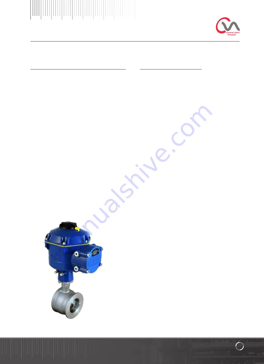
CVQ Linear Actuator

Refer to the actuator nameplate for it’s specific approval details

The CVA is built in accordance with: -

European—Hazardous Area ATEX (94/9/EC) II 2 c T4 GD

Ex d IIB T4 Gb, Ex t IIIC T120°C Db

EN60079-0, EN60079-1, EN13463-1,  
EN13463-5 and EN61241-1 
Ambient Temperature Range:  
-20 °C to +60 °C (-4 °F to +140 °F) 
*Option -40 °C to +60 °C (-40 °F to +140 °F)

Ex d IIC T4 Gb, Ex t IIIC T120°C Db

EN60079-0, EN60079-1, EN13463-1,  
EN13463-5 and EN61241-1 
Ambient Temperature Range: 
-20 °C to +60 °C (-4 °F to +140 °F) 
*Option -40 °C to +60 °C (-40 °F to +140 °F)

Ex de IIB T4 Gb, Ex t IIIC T120°C Db

EN60079-0, EN60079-1, EN60079-7,  
EN13463-1, EN13463-5 and EN61241-1 
Ambient Temperature Range: 
-20 °C to +60 °C (-4 °F to +140 °F) 
*Option -40 °C to +60 °C (-40 °F to +140 °F)

Ex de IIC T4 Gb, Ex t IIIC T120°C Db

EN60079-0, EN60079-1 and EN60079-7, 
EN13643-1, EN13463-5 and EN61241-1
Ambient Temperature Range:  
-20 °C to +60 °C (-4 °F to +140 °F)
*Option -40 °C to +60 °C (-40 °F to +140 °F)

International-Hazardous Area IECEx

Ex d IIB T4 Gb, Ex t IIIC T120°C Db

IEC60079-0, IEC60079-1 and IEC61241-1 
Ambient Temperature Range:  
-20 °C to +60 °C (-4 °F to +140 °F) 
*Option -40 °C to +60 °C (-40 °F to +140 °F)

Ex d IIC T4 Gb, Ex t IIIC T120°C Db

IEC60079-0, IEC60079-1 and IEC61241-1 
Ambient Temperature Range:  
-20 °C to +60 °C (-4 °F to +140 °F) 
*Option -40 °C to +60 °C (-40 °F to +140 °F)

Ex de IIB T4 Gb, Ex t IIIC T120°C Db

IEC60079-0, IEC60079-1, IEC60079-7 and IEC61241-1 
Ambient Temperature Range:  
-20 °C to +60 °C (-4 °F to +140 °F) 
*Option -40 °C to +60 °C (-40 °F to +140 °F)

Ex de IIC T4 Gb, Ex t IIIC T120°C Db

IEC60079-0, IEC60079-1, IEC60079-7 and IEC61241-1 
Ambient Temperature Range: 
-20 °C to +60 °C (-4 °F to +140 °F) 
*Option -40 °C to +60 °C (-40 °F to +140 °F)

FM. Explosionproof, Class I, Div 1, Groups C & D, T4

Ambient Temperature Range:  
-20 °C to +60 °C (-4 °F to +140 °F) 
*Option -40 °C to +60 °C (-40 °F to +140 °F)

FM. Explosionproof, Class I, Div 1, Groups B, C & D, T4

Ambient Temperature Range:  
-20 °C to +60 °C (-4 °F to +140 °F) 
*Option -40 °C to +60 °C (-40 °F to +140 °F)

FM. Dust Ignitionproof, Class II, Div 1, Groups E, F & G, T4

Ambient Temperature Range:  
-20 °C to +60 °C (-4 °F to +140 °F)
*Option -40 °C to +60 °C (-40 °F to +140 °F)

Summary of Contents for CVQ 1200

Page 1: ...ublication P175E Issue 04 09 CVQ Range Established Leaders in Valve Actuation Electric Actuators and Control Systems This Manual contains important safety information Please ensure it is thoroughly re...

Page 2: ...2...

Page 3: ...otork CVA range helps to maximize product quality and plant capacity CVA range actuators are self contained purpose designed and built for continuous remote electrical operation of control valves This...

Page 4: ...lating to the specific Hazardous Area Only Rotork approved actuator replacement parts should be used Under no circumstances should any modification or alteration be carried out on the actuator as this...

Page 5: ...140 F Option 40 C to 60 C 40 F to 140 F International Hazardous Area IECEx Ex d IIB T4 Gb Ex t IIIC T120 C Db IEC60079 0 IEC60079 1 and IEC61241 1 Ambient Temperature Range 20 C to 60 C 4 F to 140 F O...

Page 6: ...the protection afforded by the actuator Where appropriate the user must ensure the actuator is suitably protected against its operating environment WARNING OPERATING BY HAND Where actuators are suppl...

Page 7: ...ed immediately store it in a dry place until you are ready to connect incoming cables If the actuator has to be installed but cannot be cabled it is recommended that any plastic transit cable entry pl...

Page 8: ...ork products Read and save all instructions prior to installing operating and servicing this product If you don t understand any of the instructions contact Rotork for clarification Follow all warning...

Page 9: ...remotely Note when STOP or RUN is selected the control knob will rotate between the two positions without having to depress the locking latch It is also possible to lock the selector in the RUN or ST...

Page 10: ...ection Run Blue Slow Flash Bluetooth Communication Active Green Blue Alternate Flash Run or Test Bluetooth communication active No faults Red Blue Alternate Fast Flash Initiating Bluetooth connection...

Page 11: ...wer Pack Assembly please note that the actuator output shaft may move after removal of the power supply Move the Knob Selector to the STOP position to prevent any unwanted electrical movement before c...

Page 12: ...is free and is available for download from the Rotork website at www rotork com CAUTION It is essential that the setup procedure is carried out when the valve is not under working process conditions a...

Page 13: ...t limits of travel Valve Actions Set Output Torque and End of Travel Options Input Output Setup Set Demand Feedback Parameters Fail Modes Set Loss of Power Signal Failure Modes Advanced 1 Set back off...

Page 14: ...eck the Drive bush for fit and orientation against the valve stem before assembly Whilst the Drive Bush is removed it is possible to note the position of the actuator output shaft Fig 16 4 shows the a...

Page 15: ...t be provided to mount the unit to the valve top works assembly Actuator to mounting flange assembly fixings must conform to Material Specification ISO Class 8 8 Delta GZ coated Grade A4 stainless ste...

Page 16: ...An internal earthing point is provided for water tight applications In addition a mandatory 6mm external earthing stud is provided for all explosion proof applications Removing Terminal cover Using an...

Page 17: ...ype 160292 ring tabs for power and earth terminals and AMP type 34148 ring tabs for the control terminals Refer to the wiring diagram to identify functions of terminals Check that the supply voltage i...

Page 18: ...ons It is now required to establish communications in order to complete the fitting procedure Ensure Bluetooth is enabled on the PDA then click on the Enlight Icon to start the program The maximum ran...

Page 19: ...hed it is necessary to log in There are three levels of login with password protection to limit higher level access View Allows review of actuator settings only No changes can be made Password view Us...

Page 20: ...he actuator serial number current valve stroke and position are also displayed WARNING The default setting of a new actuator is minimum torque and clockwise to close If the actuator has previously bee...

Page 21: ...lve tight shutoff is required Limit Stop the actuator at the set limit where valve does not require tight shutoff Select the START option to save changes Select basic parameters and torque limit setti...

Page 22: ...y 1 for coarse and 0 1 for fine control When the position control is operated for the first time a warning will appear to indicate that the actuator will be taken offline and will not respond to remot...

Page 23: ...are factory set to give a nominal travel of 90 degrees Adjustment for non seating valve types For closed and open stop position adjustment Undo stop bolt locknut Move actuator and valve to the requir...

Page 24: ...hrough stroke Set basic actuator parameters The MOV tag can be edited Use the keyboard to edit the MOV tag field Shaft Action Select direction to close the output shaft to suit valve operation Close O...

Page 25: ...ion and end stops are correctly set or damage to the valve may occur Fig 27 2 Fig 27 1 AUTO LIMIT will initiate the auto setting procedure FIXED LIMIT will allow the actuator to find the closed limit...

Page 26: ...tor will then turn its output shaft away from the Closed limit of travel and repeat the procedure to eliminate any inertia effects and re adjust the end of travel limit as necessary Finding the Open L...

Page 27: ...w complete and both ends of travel tight shut off limits have been defined and set PDA screen will return to the Stroke Set up menu If no further settings are required move the Mode selector to the ST...

Page 28: ...rque and End of Travel Options Input Output Setup Set Demand Feedback Parameters Fail Modes Set Loss of Power Signal Failure Modes Advanced 1 Set back off Indication Relay Functions Advanced 2 Set Bum...

Page 29: ...torque Close value 40 torque Increase the torque if necessary Set Basic Actuator Parameters The MOV tag can be edited by using the keyboard at the bottom of the screen Shaft Action Select direction to...

Page 30: ...ts during loss of Bluetooth commands or when navigating between screens It is now possible to turn the output shaft to the desired Position using the position control slider CAUTION The actuator will...

Page 31: ...ose Limit Use the Position Control Slider to move the actuator output shaft to the required Closed position Click on the Set Close box to calibrate the closed limit of travel The Set Close and the Ser...

Page 32: ...el The Set OPEN and the Serial number boxes are greyed out during the calibration procedure and indicate acceptance of the new settings when cleared The new open limit position is now shown on the mai...

Page 33: ...al Failure Modes Advanced 1 Set back off Indication Relay Functions Advanced 2 Set Bumpless Transfer Functions Characterisation Modify Actuator Response against Demand profile Configurations Options S...

Page 34: ...nfig to CVA Upload the current configuration stored from the PDA to the actuator The Transferring data screen will be active during the download Load Config from File VIEW Use this screen to load a co...

Page 35: ...or configuration to a file location on the PDA Save config to file will open a new screen to save file in PDA File will be identified by actuator serial number This can be edited The file location can...

Page 36: ...ure Analogue demand and Feedback options Fail Modes Configure Power and loss of signal failure actions Advanced 1 Configure backoff and status relay options Advanced 2 Configure bumpless transfer opti...

Page 37: ...as required Shaft Action Clock or Anticlock to close Clock is Default Close Open Stop Set the end of travel stop function for Torque or Limit to suit the characteristics of the valve Torque The actua...

Page 38: ...calibrate The setpoint will be calibrated to the Measured Demand mA value displayed in the box Open Demand mA Calibration Set mA Demand level at fully Open position Apply maximum 100 Setpoint Signal t...

Page 39: ...ition Power Failure Delay Delay before failsafe action is adjustable up to a maximum of 10 seconds NOTE The LED on the mode selector will remain illuminated until the Reserve Power Pack failsafe capac...

Page 40: ...es the lowest level analogue mA setpoint as a percentage that will fully open the valve The example shown in Fig 42 2 states that a 99 5 or greater control request will give a tight shut off open on t...

Page 41: ...within the actuator control or valve Open Limit Active when the actuator is at the Fully Open position Closed Limit Active when the actuator is at the Fully Closed position Open Thrust Active when th...

Page 42: ...r movements from being counted as these are considered too small to cause valve wear The default setting is 0 25 of overall valve travel Total Direction Changes Before Alarm Can be used to generate an...

Page 43: ...and Signal is Linear by default Use the Valve Characteristic drop down menu to select between the following Linear The actuator position responds directly to the mA demand request Quick Opening The ac...

Page 44: ...against demand profile can be tailored to suit the valve application by plotting the characteristic at up to 20 co ordinate points on the graph Click on the Valve Position box and highlight the requir...

Page 45: ...anges to the actuator configuration Change Password This menu allows the actuator password to be changed Note If the actuator Password is changed it will not be possible to communicate with the unit u...

Page 46: ...Input Output Setup Set Demand Feedback Parameters Fail Modes Set Loss of Power Signal Failure Modes Advanced 1 Set back off Indication Relay Functions Advanced 2 Set Bumpless Transfer Functions Charac...

Page 47: ...nd will override any system commands Click on OK to initiate manual override Setpoint Feedback Displayed as position and percentage the Setpoint and Feedback are updated continuously during actuator m...

Page 48: ...open close torque and dwell time Dwell time is total time spent at any position during the valve stroke To download a file click on READ Note Only open one graph at a time as this can affect the scal...

Page 49: ...it is possible to set a reference stroke to record torque This can be compared against a current recording to determine if any parameters have changed Set Reference stroke Will record the last valve...

Page 50: ...o the current settings When the compare screen appears click onto the compare box and you will be prompted to find a previously stored configuration file When the file is opened a list will be generat...

Page 51: ...If your Rotork actuator has been correctly installed and sealed it will give years of trouble free service Should you require technical assistance or spares Rotork guarantees the best service in the...

Page 52: ...Rotork recognises all registered trademarks Published and produced in the UK by Rotork Controls Limited POWTG0409 A full listing of our worldwide sales and service network is available on our website...

Reviews: