background image

Device functions

Page 30

RES-5008

Version 2

9.5

Menu items

Labelling

Description

Adjustment range

°C

Home position

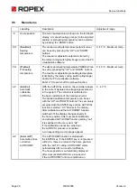
The current actual value is shown on the terminal's 
display. A manual heating process (to the adjusted 
sealing or preheating temperature) can be started 
by pressing the “HAND” button.

SH

[

S

eal

H

eat]

Sealing 
temperature

The desired sealing temperature (setpoint value) 
can be set by pressing the “UP” and “DOWN” 
buttons.
The maximum adjustable setpoint is limited by 
the rotary coding switch (alloy/range) and/or the PC 
visualisation software.

0, 40 °C…Maximum temp.

PH

[

P

re

H

eat]

Preheating 
temperature

The desired preheating temperature PREHEAT can 
be set by pressing the “UP” and “DOWN” buttons.
The maximum adjustable preheating temperature 
is limited by the rotary coding switch (alloy/range) 
and/or the PC visualisation software.
Enter 0 °C to switch off the preheat function.

0, 40 °C…Maximum temp.

AC

[

A

uto

C

al]

Automatic 
calibration 
AUTOCAL

With the AUTOCAL function, the controller adapts 
to the current signals and voltage signals present 
in the system. The controller is calibrated to 
the basic resistance of the heating element.
The desired calibration temperature can be set 
with the “UP” and “DOWN” buttons. The set value is 
accepted with the ENTER key and the AUTOCAL 
function is started. “AC” flashes in the display. 
After calibration and the AUTOCOMP function 
switched off, the display changes directly to 
the home position. After successful calibration 
and activated AUTOCOMP function (setting “on"), 
it is switched to the menu item “AP”.
If the calibration cannot be carried out, 
the AUTOCAL process is cancelled. 
A corresponding error message appears.

0…40 °C

AP

[

A

utocom

P

]

Automatic phase 
correction 
AUTOCOMP

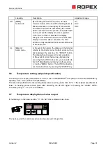
The AUTOCOMP function is started with 
the ENTER key. If the ENTER key is not pressed 
within 2 s, there is a return to the home position. 
With the “AUTO” setting, AUTOCOMP starts 
automatically after successful calibration.
The home position is automatically displayed 
after a successful AUTOCAL process and 
if the AUTOCOMP function is switched on.

Summary of Contents for RESISTRON RES-5008

Page 1: ...ng AUTOCAL Automatic optimisation AUTOTUNE Automatic configuration of the secondary voltage and current range AUTORANGE Automatic phase correction AUTOCOMP Automatic frequency adaptation Booster output standard Analogue output 0 10 VDC for ACTUAL temperature 24 VDC control signals for START and PREHEAT with electrical isolation Alarm function with error diagnosis Heating element alloy and temperat...

Page 2: ...d operation 20 8 1 Device view 20 8 2 Device configuration 20 8 3 Burning in and changing the heating element 22 8 4 Commissioning rules 24 9 Device functions 26 9 1 Display elements and operating elements 26 9 2 Display image of the T 408 1 terminal 27 9 3 Menu navigation 28 9 4 Menu structure 29 9 5 Menu items 30 9 6 Temperature setting setpoint specification 31 9 7 Temperature display Actual va...

Page 3: ...Version 2 RES 5008 Page 3 10 Factory settings 55 11 Maintenance 56 12 Disposal 56 13 Technical data 57 14 Dimensions 59 15 Modifications MODs 60 16 How to order 61 17 Index 63 ...

Page 4: ...e safe operation please observe the safety and warning information included in the operating instructions 2 2 Drawings and illustrations The drawings and illustrations in these operating instructions are exemplary Many details are presented in a sim plified manner 2 3 Copyright All contents in particular texts photographs and graphics are protected by copyright All rights including to rep lication...

Page 5: ...ply to information units smaller than the section related warning notices Embedded warnings are structured as follows SIGNAL WORD Instructions to avoid a dangerous situation 3 1 4 Meaning of the hazard symbols The hazard symbols in the warning notices have the following meanings Signal word Importance Imminent danger Consequence Death or serious injuries Possibly imminent danger Consequence Death ...

Page 6: ...derstood the operating instructions important information on the correct handling of the product WARNING Danger to life and danger of serious physical injuries as well as property damage if all warnings regulations and information are not followed Strictly follow all warnings regulations and information in these operating instructions WARNING Danger to life and risk of serious physical injuries as...

Page 7: ...significantly in terms of performance and physical dimensions All information provided by us in connection with the line filter is merely intended as a guide and is based on a typical measuring setup It serves to demonstrate that compliance with the EMC directive can be achieved by using a line filter that is suitable for the overall system The line filter and current transformer must however be d...

Page 8: ...il TCR 1100 ppm K The setting or coding of the RESISTRON Temperature Controller has to be carried out according to the temper ature coefficient of the heating element used The temperature coefficient must be taken from the ROPEX application report and must be set accordingly More information High resistance heating elements such as NiCr 80 20 are not suitable for an operation with a RESISTRON Temp...

Page 9: ...system In order to avoid malfunctions only the original ROPEX current transformers or ROPEX monitoring current trans formers may be used The current transformer may be operated only if it is correctly connected to the RESISTRON Temperature Con troller See Chapter Start up The safety related information in the Mains connection chapter must be observed External monitoring modules can be used to incr...

Page 10: ...or the components listed in the application report If you cannot judge whether your material can be sealed or what cycle rate is possible we can also create sealing samples for you We will then use our system and your material to check the possibility for sealing and incorporate the findings into the application report In this case you are welcome to contact info ropex de Your request will then be...

Page 11: ...nd parameters and also to display important controller information The ACTUAL temperature of the heating element is output through the operator terminal and through an analogue output 0 10 VDC The real heating element temperature can be visualised on an additional external display instrument The RES 5008 has an integrated error diagnosis The error diagnosis checks the external system heating eleme...

Page 12: ... the RESISTRON Temperature Controller RES 5008 1 Switch off mains voltage and 24 VDC power supply verify lack of voltage 2 Installation of the RESISTRON Temperature Controller in the switching cabinet on a TS35 top hat rail in accordance with EN 60715 If several devices are mounted the minimum distance specified in section 12 Disposal on page 56 must be maintained 3 Installation of the operator te...

Page 13: ...rcurrent protective devices must be provided for the regulator and the sealing application ROPEX application report The overcurrent protective device must be located in the immediate vicinity of the device In the ROPEX application report the smallest possible specification for this overcurrent protection device is specified based on the calculated currents If the protection device is dimensioned d...

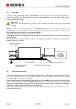
Page 14: ...e system prone to errors in the long term Line Impulse transformer Current transformer PEX W4 W5 U prim 1 Heatsealing band R f T U sec 2 A F Avoid long cables Heatseal element with coppered ends Use heatseal bands with suitable temperature coefficient 20 mm clearance if several controllers installed on one top hat rail No additional resistance in secondary circuit Dimension transformer correctly S...

Page 15: ...crease machine safety by switching off the load on all poles in the event of a fault e g in combination with the ALARM output of the RESISTRON Temperature Controller Dimensioning ROPEX application report I1max for Ka and Kb Impulsetransformer Design according to EN 61558 or UL 5058 isolating trans former with reinforced insulation Ground core CAUTION Use only single chamber design Power ED number ...

Page 16: ...ctions in the section 7 3 Mains connection on page 15 with regard to cabling must be complied with Example drawing for LF 06480 7 5 Current transformer The current transformer PEX W4 W5 appropriate for RESISTRON Temperature Controller is part of the control system The current transformer may be operated only if it is correctly connected to the temperature controller section 7 3 Mains connection on...

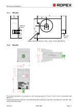
Page 17: ...hat rail measuring 35 x 7 5 mm or 35 x 15 mm in accordance with EN 60715 If the high current line cannot be conducted through the opening provided due to the diameter an HCB 1 high current rail must be used Snap on for DIN rail 35 x 7 5mm or 35 x 15mm EN 60715 terminal block terminal wires 14 60 24 75 14 23 28 26 39 12 ...

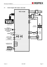
Page 18: ... 8 4 3 2 1 IR UR Heat sealing band sec U2 prim U1 twisted Line filter ALARM OUTPUT max 30 V 1 A Ground Must be grounded externally to pre vent electrostatic charging 17 C ATR _ ANALOG OUTPUT 0 10 VDC 14 13 12 6 7 16 18 BOOSTER OUTPUT HO LD PREHEAT SEALHEAT ENTER HAND RESET ROPEX Display and operation panel T 408 PREHEAT with 24 VDC signal START HEAT with 24 VDC signal 15 7 ...

Page 19: ...ing band sec U2 prim U1 twisted ALARM OUTPUT max 30 V 1 A Ground Must be grounded externally to pre vent electrostatic charging 17 C ATR _ ANALOG OUTPUT 0 10 VDC 14 13 12 6 7 16 18 HO LD PREHEAT SEALHEAT ENTER HAND RESET ROPEX Display and operation panel T 408 PREHEAT with 24 VDC signal START HEAT with 24 VDC signal LINE 4 3 2 1 15 prim U1 Booster 2 4 IN OUT 1 3 Line filter twisted Length max 1 m ...

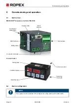
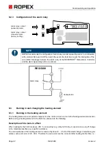
Page 20: ...S 5008 Terminal T 408 1 8 2 Device configuration NOTE The regulator must be switched off to configure the coding switch and the slide switch Connection terminals Display LEDs Coding and Rating plate Terminal plan Slide switch USB interface Circuit Terminal Indicator display Operating keys Cable connection Fastening Rating plate hooks 4x ...

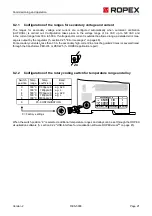
Page 21: ...hrough the transformer PEX W4 or PEX W5 ROPEX application report 8 2 2 Configuration of the rotary coding switch for temperature range and alloy When the switch position 9 is selected additional temperature ranges and alloys can be set through the ROPEX visualisation software section 9 22 USB interface for visualisation software ROPEXvisual on page 45 2x 0 5 1 2 3 4 6 7 8 9 AUX CONFIGURATION ALARM...

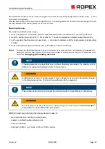
Page 22: ...e cold resistance of the heating element is reduced by about 2 3 But this small change in resistance gen erates a zero point error of 20 30 K Therefore the zero point must be corrected after heating the first time i e NOTE ROPEX recommends the configuration Alarm relay contact opened by alarm in combination with contactor Kb to switch off the load in the event of a fault As a result the interrupti...

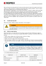
Page 23: ... The burn in effect described here does not need to be considered if the manufacturer pre treated the heating element for this purpose The thermal pre treatment is described as burned in at ROPEX in the article text Changing the heating element ROPEX recommends changing the heating element in case of mechanical defects bending or deformations scaled or oxidised heating element ends burned in depos...

Page 24: ...equirement Device is correctly mounted and connected section 6 Transport and Storage on page 12 Proceed as follows when commissioning the regulator RESISTRON Temperature Controller RES 5008 for the first time 1 Switch off mains voltage and 24 VDC power supply verify lack of voltage 2 Make sure that there is no 24 V START signal present 3 Switch on the mains voltage and 24 VDC power supply in any o...

Page 25: ...Device configuration on page 20 ROPEX application report After the device configuration is correct perform zeroing again 7 After successful zeroing specify a defined temperature at the setpoint temperature and apply the START signal HEAT The SEALHEAT LED on the Terminal T 408 1 and the HEAT LED at the regulator light up The actual temperature is shown on the display of the T 408 1 terminal Thus th...

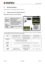
Page 26: ...s with a different frequency Incorrect too low supply voltage OUTPUT green In control operation the light intensity is proportional to the heating current HEAT yellow START requested but function is blocked START is carried out ALARM red Configuration error AUTOCAL not possible Regulator incorrectly calibrated carry out AUTOCAL Error Chapter 9 25 OUTPUT green LED AC HEAT yellow LED yellow LED ALAR...

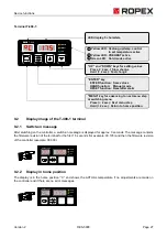
Page 27: ...re if no adjustments are made on the controller and if there are no error messages ENTER function HAND function RESET function Yellow LED 1 Yellow LED 2 Green LED 3 ENTER key Save values Manual mode Reset after alarm Heatung up temp control to set temperature active PREHEAT active Hold mode active HOLD PREHEAT SEALHEAT ENTER HAND RESET ROPEX 2 3 T 408 1 LED display 5 characters UP and DOWN keys fo...

Page 28: ...is in alarm state Then there is a return to the alarm menu If no key is pressed for 30 s there is a return to the home position Exception There is no automatic return from the positions AC AutoCal and AL ALarm after waiting for 30 s 9 3 2 Menu navigation in the event of an alarm In the event of an alarm the display on the terminal returns to the Alarm menu Errors can be acknowledged by pressing th...

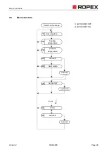
Page 29: ... 5008 Page 29 9 4 Menu structure Autocal AC Autocal SH Sealing temperature Home position Switch on message Error Autocal AC Autocal C AL Alarm Autocomp AP Autocomp 1 2 1 AUTOCOMP OFF 2 AUTOCOMP ON HO Hold mode PH Preheat temperature ...

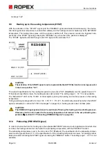
Page 30: ...bration AUTOCAL With the AUTOCAL function the controller adapts to the current signals and voltage signals present in the system The controller is calibrated to the basic resistance of the heating element The desired calibration temperature can be set with the UP and DOWN buttons The set value is accepted with the ENTER key and the AUTOCAL function is started AC flashes in the display After calibr...

Page 31: ...of the heating phase is saved and shown on the display of the terminal The active hold mode is indicated by the HOLD LED on the terminal This process is repeated with each cycle and the displayed value is updated If the On2 function is selected the display changes from Hold mode back to the actual value display in real time after 2 seconds The hold function is only reactivated for 2 seconds at the...

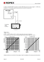
Page 32: ...rrelation between the change in the output voltage and the ACTUAL temperature is linear A display instrument can be attached to this analogue output for visualisation of the heating element temperature RES 5008 Actual value output 0 10 VDC 7 17 0 V Temperature display e g ATR 3 0 10 VDC Max 5 mA 0 300 C range 2 3 4 5 6 7 8 9 10 300 Temperatu re T C VDC Voltage U 60 90 120 150 180 210 240 270 1 20 ...

Page 33: ...terminal 17 7 goes to 0 3 C i e approx 0 VDC The AUTOCAL function is executed maximum 3 times if the temperature of the heating element fluctuates After that if the function cannot be successfully ended an error message is output section 9 25 Error messages on page 48 The AUTOCAL function must be executed if the heating element has been changed or the wiring has been changed In case the ambient te...

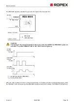
Page 34: ... up during the heating and control process on the sealing temperature During a warning message with error nos 104 105 111 113 211 the alarm relay is switched when the START signal is activated section 9 25 Error messages on page 48 A heating process does not take place CAUTION The PREHEAT Signal preheat must be switched off during this heating and controlling process Otherwise it will not be heate...

Page 35: ...the T 408 1 terminal lights up When the home position is shown on the terminal display it is heated up to the set preheat temperature while the MANUAL button is pressed and the PREHEAT signal is activated Accordingly the PREHEAT LED lights up RES 5008 Max 6 mA 18 7 PREHEAT GND 24 VDC PREHEAT PREHEATING HIGH 12 VDC LOW 2 VDC START Signal ACTUAL temperature PREHEAT Signal 24 VDC 24 VDC T2 T1 T1 preh...

Page 36: ...home position is shown in the display the current ACTUAL temperature at the end of the last sealing phase is always shown After the regulator is switched on the real ACTUAL temperature is displayed until the end of the first heating phase 3 On2 At the end of a sealing phase the current ACTUAL temperature is displayed as a display value for another 2 seconds Subsequently the ACTUAL temperature is d...

Page 37: ...heit The unit for the temperature display and temperature input can be switched between Celsius C and Fahrenheit F The display of the T 408 1 terminal must be in the home position NOTE The temperature unit can be changed while the RESISTRON Temperature Controller RES 5008 is in operation ACTUAL temperature START Signal 24 VDC T t t 0 0 Hold OFF T t 0 ACTUAL display Hold On T t 0 Hold On2 T t 0 Hol...

Page 38: ... of the TCR value and thus a better matching of the temperature display of the controller and the real temperature of the heatsealing band To calculate the TCR value the temperature at the heatsealing band is measured in control mode START signal active using an external temperature sensor e g a thermocouple The measured temperature is transferred to the temperature controller by means of the ROPE...

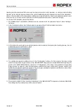
Page 39: ...opened with the TCR Calculator icon button 3 In this surface the externally measured temperature can be entered During an active heating process the cal culated temperature coefficient is output 4 The variable temperature coefficient is set in the Configuration surface For this purpose the rotary coding switch for temperature range and alloy on the RESISTRON Temperature Controller RES 5008 must be...

Page 40: ...an also be ordered as a modification from ROPEX section 15 Modifications MODs on page 60 The modification is then listed on the nameplate of the controller so that the technical change is visible 9 14 Automatic phase correction AUTOCOMP Default setting AUTOCOMP off The AUTOCOMP function can be activated for use with the ROPEX visualisation software section 9 22 USB interface for visualisation soft...

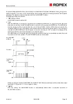
Page 41: ...TOCAL function Within these 2 seconds the AP AutocomP is shown in the display of the terminal and the three decimal points light up The subsequent execution of AUTOCOMP lasts only for approx 2 seconds In doing so AP is shown in the display of the terminal and the three decimal points light up one after the other If the ENTER key is not pressed within 2 seconds after AUTOCAL has been successfully e...

Page 42: ...in the specified tolerance band the temperature diagnosis is switched on If the ACTUAL temperature leaves the tolerance band the related error nos 307 308 are output and the alarm output switches on section 9 25 Error messages on page 48 If the temperature diagnosis has not been activated before the START signal is deactivated i e the ACTUAL tem perature has not exceeded the lower tolerance band l...

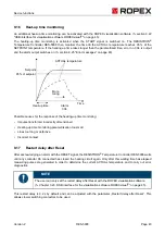
Page 43: ...er incorrectly dimensioned Heating up time monitoring parametrisation too small Lines too long or defective Incorrect contact 9 17 Restart delay after Reset After acknowledging an alarm with the RESET signal the RESISTRON Temperature Controller RES 5008 waits until any contactor Kb connected has closed the heating circuit again Only after this waiting time has elapsed measuring pulses are generate...

Page 44: ... impulse transformer is too large or if the sealing temperatures are low 9 19 Communication failure between controller and terminal If the data communication between RESISTRON Temperature Controller RES 5008 and the T 408 1 terminal is disrupted or interrupted this is shown by a special display rotating display segments on the terminal s display The following options are included as reasons for a ...

Page 45: ...impulse current 25 A The switching amplifier must be connected in accord ance with section 7 7 Circuit diagram with booster connection on page 19 CAUTION In order to avoid the EMC interference the connection cable to the external switching amplifier may not exceed a length of 1 m and has to be twisted 9 22 USB interface for visualisation software ROPEXvisual A USB interface type micro USB is avail...

Page 46: ...ot available 9 24 System monitoring alarm output To increase the operational safety and to avoid incorrect seals the RESISTRON Temperature Controller RES 5008 has a differentiated error message and diagnosis Both the outer wiring and the internal system are monitored by hardware and software measures The system monitoring supports the operator in localising a defective operating status A system ma...

Page 47: ...y on page 22 these statuses are inverted D Output of the error number via the actual value output 0 10 VDC terminals 17 7 As a temperature display is not required in case of malfunction the actual value output is used to output the error in case of alarm 13 voltage levels are available within the 0 10 VDC range An error number is assigned to every voltage level section 9 25 Error messages on page ...

Page 48: ...error diagnosis via the actual value output Internally in the regulator the error messages are differentiated in even more detail 3 digit error numbers are also displayed with the ROPEX Visualisation software section 9 22 USB interface for visualis ation software ROPEXvisual on page 45 The error search can thus be performed even more effectively CAUTION Evaluation of the actual value output for de...

Page 49: ...307 Temperature too low leave the tolerance band Chap 9 15 Check the dimensioning of the impulse trans former Check heat removal through the sealing process Verify application through sealing tests 308 Temperature too high leave tolerance band Chap 9 15 309 Temperature too low tolerance band not reached Chap 9 15 310 Temperature too high tolerance band not reached Chap 9 15 5 201 3 33 Line frequen...

Page 50: ...device 915 916 917 Incorrect slide switch for alarm output Check slide switch Check slide switch 918 Part 1 of 3 Error messages faults NOTE The specified error messages are output as faults Actual value output displays constant error voltage Alarm LED lights up continuously Alarm relay is active Error no Actual value output Voltage V Cause Measure during initial startup Measure during machine oper...

Page 51: ...uring machine operation heating element not changed 8 104 5 33 10 Current signal incorrect Impulse transformer incorrectly dimensioned Perform AUTOCAL Check transformer specification Error ranges Error ranges Loose contact 105 Voltage signal incorrect Impulse transformer incorrectly dimensioned Strong harmonic waves on mains supply 106 Voltage and current signal incorrect Impulse transformer incor...

Page 52: ...Error range Check configuration Error ranges Loose contact 11 112 7 33 10 Voltage signal incorrect Calibration not possible Error range Check configuration Error ranges Loose contact 12 113 8 00 10 Voltage current signal incorrect Calibration not possible Error ranges Check configuration Error ranges Loose contact 13 114 8 66 10 Temperature fluctuates Calibration not possible Perform AUTOCAL and o...

Page 53: ...up point Wire break Secondary winding of the impulse transformer interrupted UR signal missing Measurement cable interrupted Partial short circuit Delta R Heating element is partially bridged through a conducting part downholder counter bar etc Interruption of the parallel circuit Wire break heating element break Contacting at the heating element defective Complete short circuit Heating element in...

Page 54: ...rs during operation Before initiating a thorough search for a loose contact you should first check all connections for a good and tight fit Among others weak spots can be plugs and very often clamping heads screw connections and cable lugs Requirements for looking for loose contacts We recommend having an electrician to troubleshoot the machine and an employee to operate the machine A continuous S...

Page 55: ... out the AUTOCAL function and repeat the five steps listed above to locate the loose contact If the measures described has not led to success please contact us directly info ropex de and send the fol lowing information to Date and number of the application report and if applicable project name as well as the used page and column Actual implementation of the sealing application in the machine if th...

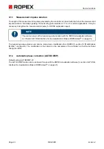
Page 56: ...per disposal take the device to the municipal collection points provided for this purpose Observe the local regulations Careless and uncontrolled disposal can cause damage to the environment and human health Help protect the environment and human health and dispose of the product or recycle it responsibly Measurement impulse duration Measurement impulse duration 1 7 ms Automatic Phase correction A...

Page 57: ...th must not exceed 300 VAC Power supply Symmetrical TN or TTsystem Overvoltage category III CAUTION Operation in voltage free system e g IT system only after checking with ROPEX Line frequency 47 63 Hz automatic frequency adjustment in this range Current consumption Primary current of the impulse transformer Imax 5 A ED 100 Imax 25 A ED 20 cycle duration 1 min A booster must be used for higher cur...

Page 58: ...500 C Accuracy 1 plus 50 mV Alarm relay Terminals 12 13 14 Umax 30 V DC AC Imax 1 A changeover contact potential free Power loss Max 20 W MTTF as per ISO 13849 1 1522 years see EN ISO 13849 1 table C 3 Triacs Ambient conditions Maximum altitude 2000 m Ambient temperature 5 45 C Maximum relative humidity 80 at temperatures up to 31 C decreasing linearly to 50 relative humidity at 45 C Degree of pro...

Page 59: ...igid or flexible 0 2 2 5 mm AWG 24 12 Through pluggable terminals Pluggable terminals Tightening torque 0 5 0 6 Nm Screwdriver SZS 0 6x3 5 mm CAUTION If ferrules are used they must be crimped in accordance with DIN 46228 and IEC EN 60947 1 Otherwise correct electrical contact in the termi nals is not guaranteed 75 0 90 0 113 0 135 0 ...

Page 60: ...plement special applications The modifications must be ordered separately The modification installed or configured in the controller is printed on the nameplate MOD 01 Supplemental booster for small secondary voltages UR 0 2 60 VAC This modification is e g necessary for very short or for low resistance heating elements MOD 44 Measuring impulse extension is set to 2 3 ms in the factory 42 0 90 0 48...

Page 61: ...2 5 m Art no 884205 10 m Art no 884210 Modification MOD Optional if necessary e g 01 MOD 01 art no 800001 additional booster for small voltage The article numbers of the controller and of the desired modification optional must be specified when ordering e g RES 5008 MOD 01 controller with additional gain for low voltage Order of art no 7500800 800001 Current transformer PEX W5 Art no 885107 HCB 1 ...

Page 62: ...ification Impulsetransformer For design and order specifications see ROPEX application report Design in accordance with EN 61558 in IP00 Available with UL certifications and thermal switch if necessary In addition we can individually design and offer you an series transformer Temperature display ATR 3 300 C range art no 882130 5 500 C range art no 882150 Booster B 075415 Impulse loaded 75 A 415 VA...

Page 63: ...es 53 External switching amplifier 19 62 F Fahrenheit F 37 Functional principle 11 Fuse 15 H HEAT 34 Heating element 8 Heating element type 58 Heat up time monitoring 43 High altitude 58 Humidity 58 I Impulse transformer 9 15 62 Installation 12 Installation rules 12 L LEDs 26 Line filter 9 15 16 62 Line frequency 57 Line voltage 57 M Mains connection 15 Mains frequency 11 Manual operation 31 34 Ma...

Page 64: ...emperature diagnosis 42 43 Temperature display 31 62 Temperature range 21 58 Temperature regulation 10 Temperature setting 31 Temperature unit 37 Thermal impulse process 10 Transformer 9 15 62 U Undervoltage detection 44 USB interface 45 Use 10 V Visualisation software 45 W Wiring 13 15 ...

Reviews: