Device functions
Version 2
RES-5008
Page 53
9.26
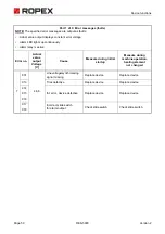
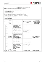
Error areas and causes
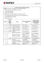
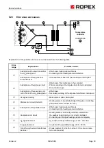
Explanations of the possible error causes can be taken from the following table.
Error
range
Explanations
Possible causes
Interruption of the load circuit after
the U
R
pickup point
- Wire break, heating element break
- Contacting at the heating element defective
Interruption of the signal from
the transformer
- I
R
measurement line from the transformer interrupted
Interruption of the primary circuit
- Wire break, Triac defective in the controller
- Primary winding of the impulse transformer interrupted
- Kb conductor open
Interruption of the secondary cir-
cuit in front of the U
R
pickup point
- Wire break
- Secondary winding of the impulse transformer interrupted
U
R
signal missing
- Measurement cable interrupted
Partial short circuit (Delta R)
- Heating element is partially bridged through a conducting
part (downholder, counter bar, etc.)
Interruption of the parallel circuit
- Wire break, heating element break
- Contacting at the heating element defective
Complete short circuit
- Heating element incorrectly installed, insulation at
the sealbar head missing or incorrectly installed
- Conducting part bridges heating element completely
U
R
signal incorrect
- U
2
outside of the permitted range of 0.4…120 VAC
I
R
signal incorrect
- I
2
outside of the permitted range of 30…500 A
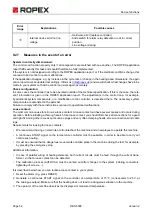
Turns through current transformer
incorrect
- Check number of turns (for current < 30 A, two or more
turns are required)
5
3
6
8
1
4
1
2
2
9
7
8
UR
IR
Temperature
controller
HARDWARE
9

