96
7 Supplement
7
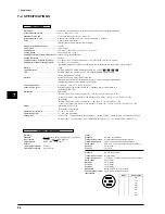
Specifications
Mechanism ..................................................
Media-movement method, Thermal-transfer serial, Automatic cartridge-changing type
Acceptable Media Width .............................
50 mm—610 mm (2"—24")
Maximum Work Area ..................................
571.6 mm x 24998 mm (22-1/2" x 984-1/8")
Acceptable Media Type ..............................
Adhesive vinyl, thickness 0.23 mm—0.06 mm (0.00906"—0.00591")
Tools ...........................................................
Cutter: blade & blade holder
Printing ribbon: thermal transfer ribbon cartridge
Number of installed cartridges ....................
6 pieces
Cutter Force ................................................
30 gf—200 gf
Cutting Speed .............................................
10 mm/sec.—200 mm/sec. (0.393"/sec.—7.874"/sec.)
Printing Speed ............................................
Max. 130 mm/sec. (5.118")
Cutting Resolution (Software Resolution) ...
0.025 mm/step (0.000984"/step)
Printing Resolution ......................................
600 dpi
Cutting Accuracy (Distance Accuracy) ........
Less than +/-0.3 % of distance traveled or +/-0.3 mm(0.0118"), whichever is greater
Registration between Printing/Cutting .........
Less than +/-0.3 mm(0.0118")
(Excluding expansion or contraction of the media, and excluding times when material is been reloaded)
Memory .......................................................
2 Mb
Control switches ..........................................
POWER, SHEET TYPE, BASE POINT/CLEAR, CUT TEST,
,
,
,
LED .............................................................
POWER, PIECE, ROLL, FRONT COVER, CARTRIDGE HOLDER, COLOR,
BUSY, BASE POINT/CLEAR
Interface ......................................................
Parallel (Centronics), Serial (RS-232C,RS-422)
(The data received first after switching on the power is used to determine automatically
whether the parallel or serial interface is being used.)
Power consumption ....................................
0.9 A/100 V, 0.8 A/117 V, 0.45 A/220-240 V
Acoustic noise level ....................................
Printing/Cutting mode: less than 60 dB (A), Standby mode: less than 40 dB (A)
(According to ISO 7779)
Dimensions .................................................
[Main unit]
1016 mm (W) x 326 mm (D) x 266 mm (H) (40" (W) x 12-7/8" (D) x 10-1/2" (H))
when cover is open: 1016 mm (W) x 326 mm (D) x 355 mm (H) (40" (W) x 12-7/8" (D) x 14" (H))
[With stand]
1016 mm (W) x 326 mm (D) x 1125 mm (H) (40" (W) x 12-7/8" (D) x 44-5/16" (H))
when cover is open: 1016 mm (W) x 326 mm (D) x 1214 mm (H) (40" (W) x 12-7/8" (D) x 44-13/16" (H))
Weight .........................................................
[Main unit] 26 kg (57.3 lb.)
[With stand] 45 kg (99.2 lb.)
Operating Temperature ...............................
15—30ºC (59—86ºF)
Operating Humidity .....................................
35—70% (non-condensing)
Accessories .................................................
• Power Cord • Thermal transfer ribbon cartridges • Blade (Carbide) • Blade Holder • Material for Test Cuts
• Head Cleaner • User's Manual • PC-60 DRIVER for windows
®
95 • PC-60 DRIVER for windows
®
3.1
Interface Specifications
[Serial]
Standard
RS-232C specifications
Transmission method
Asynchronous, duplex data transmission
Transmission speed
9600, 19200 (selected using DIP switches.)
Parity check
Odd, Even, or None (selected using DIP switches.)
Data bits
8 bits (fixed)
Stop bits
1 or 2 bits
Standard
RS-422 specifications
Transmission method
Asynchronous
Transmission speed
115.2 Kbps, 57.6 Kbps (selected using DIP switches.)
Parity check
None (fixed)
Data bits
8 bits (fixed)
Stop bits
1 bits (fixed)
Start bits
1 bits (fixed)
Handshake
Hardwire (DTR & CTS) (fixed)
Recommended Cable
Apple System Peripheral-8 Cable
Input signals
[Parallel]
Standard
In compliance with the specifications of Centronics
Input signals
STROBE (1BIT), DATA (8BITS)
Output signals
BUSY (1BIT), ACK (1BIT)
Level of
input/output signals
TTL level
Transmission method
Asynchronous
7-4 SPECIFICATIONS
PIN No.
SIGNAL NAME
1
DTR
2
CTS
3
TxD-
4
GND
5
RxD-
6
TxD+
7
N.C.
8
RxD+
8
7
6
5
4
3
2
1
+
Summary of Contents for Color Camm Pro PC-60
Page 4: ... MEMO ...
Page 6: ...2 1 Structure Spare Parts 1 1 2 FRAME 1 ...
Page 8: ...4 1 Structure Spare Parts 1 1 3 FRAME 2 ...
Page 88: ...84 4 Adjustment 4 MEMO ...


