background image

27

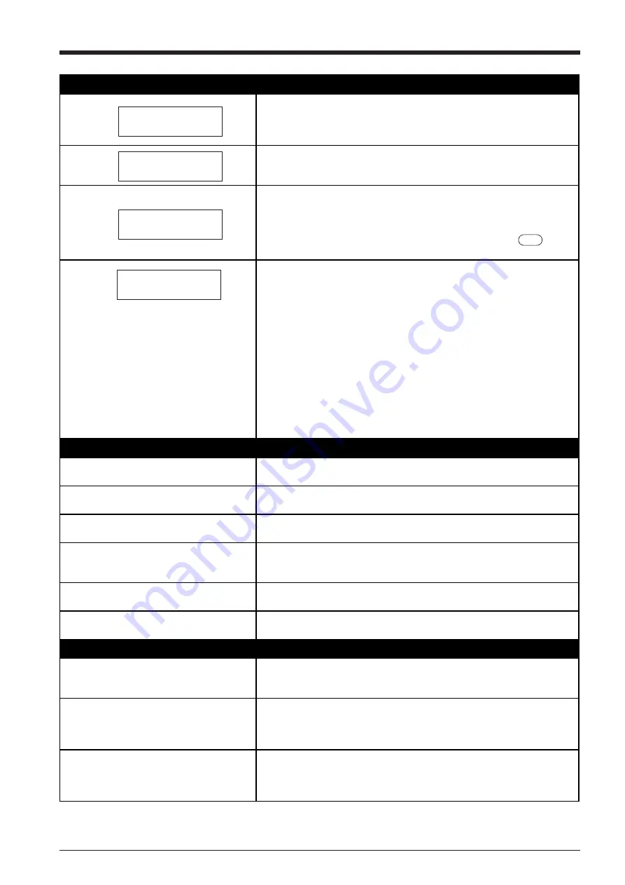
A message appears on the display

The location of one or more of the pinch rollers is not correct.

If this happens, raise the sheet loading levers and move the pinch rollers to the 
proper positions above the grit rollers.  Reposition the sheet to match this new 
alignment, then lower the sheet loading levers to hold the sheet in place.

This is displayed when the front cover is opened during cutting. Cutting 
operation is halted, and the message is displayed on the screen.

Cutting restarts when the cover is closed.

This is displayed when the material has been loaded at a position where the 
sheet sensor does not function. 

Follow the steps under "3-3 Loading Material" on page 5 to load the material so 
that it is positioned above the sheet sensor.

This is displayed when the sheet is removed after pressing the             key.

Load a sheet and press any key to cancel the error message.

Shows motor error status.

This is displayed when the PNC-1860/1410/1210 is heavily loaded, such as 
during a paper jam, when heavy stock is cut across a long distance without 
initial sheet feed, or when the sheet is abruptly pulled from the roll during 
cutting.
In this case, turn the power off and back on again (if a paper jam has occurred, 
clear the jam before turning the power back on).
For large cutting data with a roll sheet, use the “AREA” function on the display 
menu to feed the roll sheet by the length of the cut (ensure a small margin by 
setting a length that is about 0.1 m longer than the cutting data).
When using a thick sheet, change the display menu setting from "NORMAL" to 
"HEAVY."(see “8 Explanation of display menu /"NORMAL" (CUT QUALITY) . 
If the above message is displayed even after"NORMAL" (CUT QUALITY) is set 
to “HEAVY,” turn the power off and then back on again, and reduce the “**cm/
s” value in the display menu. See “** cm/s Setting cutting speed” on page 12.

The sheet is not cut properly

Are the blade and blade holder installed 
correctly and securely ?

Install these so that there is no looseness (see “3-2 Installing the cutter” on 
page 4).

Is the blade chipped ?

If it is, replace it with a new one (see  “3-2 Installing the cutter” on page 4).

Check if there are any dirty deposits on the 
blade.

If dirty, remove and clear the blade.

Are blade speed, blade compensation, and 
cutting speed appropriate for the sheet being 
cut?

Perform a cutting test and use the display menu to select the appropriate values 
(refer to “3-5 Cutting Test” on page 12).

Is a thick sheet being used?

When using a thick sheet, change the display menu setting from "NORMAL" to 
"HEAVY."

Is a wide sheet being used?

When using a sheet with a width greater than 762 mm (30"), lower the middle 
pinch roller at a position near the center of the sheet.

The sheet slips away from the pinch rollers during the cutting process

Is a sheet with sprocket holes being used?

If a sheet with holes for sprocket feed is being used, placing the pinch roller 
above the hole portion may cause the sheet to slip.  Be sure to set the pinch 
roller over the sheet to the inner side of the hole portion.

If a flat sheet (such as a standard-size sheet 
or cut sheet) has been loaded, has the 
“PIECE” setting been selected for the sheet 
type?

When loading the sheet, select “PIECE” for the “SELECT SHEET” display menu 
(refer to “3-3 Loading a Sheet” on page 9).

Is the sheet being cut blocked at some 
position?

Make sure that the left and right edges of the sheet do not touch the inner 
surfaces, front cover of the PNC-1860/1410/1210 during cutting.  Such contact 
may not only damage the sheet, but could also make normal sheet advancing 
impossible and cause the sheet to slip.

Change Pinch
Roller Position

CLOSE COVER

Sheet Set Error
Set Sheet Again

Motor Error
Power ON Again

SETUP

Summary of Contents for Camm-1 Pro GX-640

Page 1: ...This User s Manual is intended for the PNC 1860 PNC 1410 as well as PNC 1210 PNC 1860 PNC 1860 PNC 1860 PNC 1860 PNC 1860 PNC 1410 PNC 1410 PNC 1410 PNC 1410 PNC 1410 PNC 1210 PNC 1210 PNC 1210 PNC 1...

Page 2: ...tion This equipment generates uses and can radiate radio frequency energy and if not installed and used in accordance with the instructions may cause harmful interference to radio communications Howev...

Page 3: ...ND MAINTENANCE 16 5 ABOUT THE CUTTING AREA 17 6 USING THE DISPLAY MENUS 17 7 DISPLAY MENUS FLOWCHART 18 8 DISPLAY MENU LISTS 20 9 BLADES AND MATERIALS 24 10 PLOTTING ON PAPER MEDIA 25 11 WHAT TO DO IF...

Page 4: ...or death Failure to heed this message may result in serious injury or death Failure to heed this message may result in minor injury Indicates important information to prevent machine breakdown or malf...

Page 5: ...power cord from an electrical socket be sure to grip the plug The unit may tip over otherwise Install in a level and stable location Release the caster locks for the stand before attempting to move Un...

Page 6: ...nds within the space to the front or rear of the unit while in operation About the Labels Affixed to the Unit These labels are affixed to the body of this product The following figure describes the lo...

Page 7: ...t to dust high humidity or poor ventilation Do not connect to an AC outlet that supplies other than the specified voltage When the unit is not in use for an extended period detach the electrical plug...

Page 8: ...v MEMO...

Page 9: ...with the left edge of the material Movable Pinch Roller middle This is used when cutting materials with a width of 762 mm or more At this time it is set at the center of the left and right pinch rolle...

Page 10: ...ng range to be determined automatically Blinking Cursor Used to select the desired item from the menu The key moves it to the right the key moves it to the left the key moves it up the key moves it do...

Page 11: ...ble and so on so that they will not be unplugged and cause failure during operation Cables are available separately One which you are sure matches the model of computer being used should be selected S...

Page 12: ...install the blade holder Cutting quality may become poor if installed without supporting the screw in this way Tool carriage Tighten Blade holder Loosen Tool securing screw 2 Loosen the tool securing...

Page 13: ...ial sensor above the platen The size of the material cannot be determined unless the material passes over the sheet sensor 1 Position of the pinch roller middle when using material with a width of 30...

Page 14: ...410 PNS 141 PNC 1210 PNS 130 1 Install the two shafts on the sheet hanger 2 Place the roll material on top of the shafts PNC 1210 The PNC 1210 has no middle pinch roller PNC 1860 Roland DG Corp PNC 18...

Page 15: ...empting to move the pinch roller be sure to lower the sheet loading lever to raise the pinch roller Lift the sheet loading levers Move the pinch rollers to inside the edges of the sheet Stickers showi...

Page 16: ...ext press or to align the blinking cursor with the MOVE display at the lower left of the screen Press ENTER key to feed a material of the length specified in LENGTH AREA AXIS REPLOT SUBMENU Use or to...

Page 17: ...when securing a material in the unit Moving the pinch roller to the area of the grit roller and pressing the SETUP key causes the message at right to appear If this occurs raise the sheet loading lev...

Page 18: ...wing settings 6 The set length of material is fed out Make sure that the material remains held by the pinch rollers If the material does come loose from the pinch rollers set it in place again 2 3 Gui...

Page 19: ...is used When a serial connection is used however it is necessary to set the communication parameters to match those set for the computer and or software 7 Pressing the or key will sequentially display...

Page 20: ...rsor to the item to be set Then use the and keys to change the numerical value and press the ENTER key to enable the setting Setting range 0 00 mm in increments of 0 025 mm Setting range 1 85 cm s In...

Page 21: ...will begin cutting when it receives cutting data sent from computer Software Setting When cutting with commercially available application software select PNC 1860 1410 1210 as the setting for the out...

Page 22: ...ss the ENTER key to set the origin point ORIGIN SET ENTER 0 0 AREA ROTATE REPLOT SUBMENU REPLOT START CLEAR AREA ROTATE REPLOT SUBMENU REPLOT START CLEAR Repeating the same cutting The Replot feature...

Page 23: ...rtions from the completed work Tweezers You should have weed boarders or rectangles drawn around work to facilitate weeding Make sure beforehand that the surface where the work is to be stuck is clean...

Page 24: ...he pinch rollers With the sheet loading levers lowered and the pinch rollers raised use a cloth moistened with water or alcohol and wipe gently to clean Cleaning the front cover Use water or alcohol a...

Page 25: ...nu value setting screens press the MENU key To return to the previous screen without changing the numerical settings pressing the MENU key without pressing the ENTER key The pairs of allows indicate t...

Page 26: ...r LENGTH press or to move the blinking cursor to MOVE and press ENTER MENU MENU to feed the sheet at the set length ENGLISH JAPANESE GERMAN FRENCH DEMO CUT SELECT SHEET ROLL EDGE PIECE PNC 1860 Roland...

Page 27: ...Press ENTER Pressing moves the blade up or down Pressing or moves the cutter in the Y Y X or X directions respectively BAUD RATE 4800 2400 When set to SERIAL or AUTO communicati on parameter setting P...

Page 28: ...happens change the setting to OFF and perform cutting again ON NORMAL CUT QUALITY This sets the cutting quality Ordinarily this is left set to NORMAL When rapid cutting is desired such as when cuttin...

Page 29: ...the X and Y axes Compare the actual measurements of the cutting results with the data sent from the computer to calculate and set the distance adjustment value 0 00 Repeating the same cutting Deletes...

Page 30: ...omputer set this to EFFECT When set to IGNORE cutting is performed using the values for cm s and UPSPEED set at the top menu IGNORE 11 FS COMMAND To perform cutting at the tool force determined by an...

Page 31: ...are to ensure that the hands do not get caught in the tool carriage as it moves Load the material with pre printed graphics and install the alignment tool included with the PNC 1860 1410 1210 The alig...

Page 32: ...ough completely even when the tool force is increased by 50 to 60 gf more than the tool force values shown below it means that the useful life of the blade has ended Replace with a new blade Blade Mat...

Page 33: ...T and press the ENTER key Menu Settings for Plotting To perform plotting on a material of paper or the like first use the display menus to make the settings described below 1 Tool No See 7 Display Men...

Page 34: ...mory switches Interface board Communication parameters Other settings Read the computer user s manual and set it up correctly Are the computer and the PNC 1860 1410 1210 linked with the right cable Th...

Page 35: ...k on again and reduce the cm s value in the display menu See cm s Setting cutting speed on page 12 The sheet is not cut properly Are the blade and blade holder installed correctly and securely Install...

Page 36: ...ed instruction set using the control panel and this error should no longer occur Appears if the number of parameters differs from the permissible number Appears if the value specified for a parameter...

Page 37: ...ction Compati bility Instru ction Compati bility Instru ction Compati bility Instru ction Compati bility Instru ction Compati bility AA ER OE PT SP AR EW OF PU TL CA FT OH RA UC CI IM OI RR VS CP IN O...

Page 38: ...30 Automatic backspace 13 CHARACTER SET...

Page 39: ...cs compatible Serial RS 232C Buffer size 1 Mbyte Expandable up to 3 Mbyte Instruction system CAMM GL III mode1 and mode2 Switches Power switch Control switches LED POWER LED SETUP LED Display Liquid c...

Page 40: ...g conditions must be satisfied Material type 3M Scotchcal Mastercut Film ARLON Series 2100 Special stand a roll material must be set at the rear and on the inner sheet hanger Side margins 25 mm 1 or m...

Page 41: ...R9 980506...

Reviews: