


Page
8
of
21
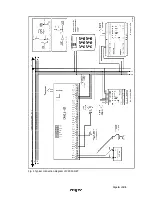
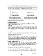
In case of 12VDC power supply, backup battery cannot be directly connected to CPR32-NET and in
such case backup power supply must be provided by 12VDC power supply unit. In case of maximal
load at supply outputs AUX (1A) and TML (0.2A), the CPR32-NET requires 20W power output.
Note: The CPR32-NET cannot be started if it is supplied only from backup battery.
Fig. 4 Connection of DC power supply for CPR32-NET
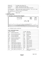
3.4 Inputs and outputs
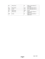
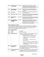
All functions can be assigned to inputs and outputs by means of PR Master software. Lists of
possible functions are specified in tables 4 and 5.
3.4.1 Inputs
All inputs (IN1...IN8) of CPR32-NET have identical electric structure and can be configured as NO or
NC lines. The NO input is triggered by shorting it to supply minus (GND) while the NC input must be
normally shorted to supply minus (GND) and it becomes triggered when connection with ground is
discontinued. Every input is internally connected (pulled up) to the power supply plus (+12V)
through a 5.6k
Ω resistor.
3.4.2 Relay outputs
CPR32-NET network controller provides two relay type outputs: REL1 and REL2 and both outputs
offer single switched contact rated 30V/1.5A. In the normal state (relay is off) the NC-COM contacts
are shorted. In the triggering state (relay is on) the NO-COM contacts are shorted. In case of power
outage, both outputs remain in the off state.
3.4.3 General purpose outputs
Six transistor outputs (OUT1...OUT6) are available in CPR32-NET network controller. All these lines
are open collector type, i.e. in the normal (off) state are pulled to supply plus via 5.6 k
Ω resistor
and when on, they short to supply minus. All lines can switch current up to 1A DC while voltage
connected to the output must not exceed 15VDC. In case of overcurrent state, transistor outputs
are automatically switched off and the network controller automatically restarts.
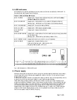
3.5 RS485 communication bus
CPR32-NET is equipped with two RS485 communication ports marked as RS485-1 and RS485-2 .
Each port includes two signal lines A and B, which can be connected to RS485 communication bus.
RS485-1 port is reserved for communication with PRxx1/PRxx2 series controllers, while RS485-2
port can be used in integration of access control system with alarm panel of INTEGRA (SATEL)
series or SALLIS (SALTO) wireless door lock system.
3.5.1 Operation with PRxx1 and PRxx2 series access controllers
PRxx1/PRxx2 series controllers are connected to CPR32-NET by means of two signal lines (A and
B), which form communication bus of access control system. Such communication bus can be freely
arranged in the form of star, tree or combination of aforementioned ones but it cannot be in the
form of loop. The matching resistors (terminators) connected at the ends of RS485 transmitting


