


Page
7
of
21
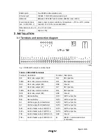
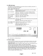
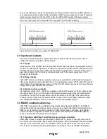
3.2 LED indicators
LED indicators are used for signalling various functions and actions conducted by CPR32-NET. In
the table below LED indicators are described.
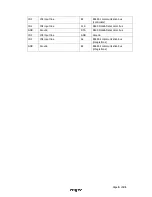
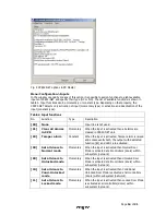
Table 3. LEDs at CPR32-NET board
LED 1: TAMPER
steady light – Tamper alarm activated (input line with function
[02]:
Tamper alarm
was activated)
LED 2: CPR ON/OFF
steady light – CPR32-NET is on (by means of PR Master software)
flashing light – CPR32-NET is off (by means of PR Master software)
LED 3: LOW BATTERY
steady light – low level of backup battery
LED 4: AC LOST
steady light – 18VAC power supply shortage
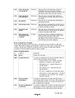
LED 5: BATTERY
FAILURE
steady light – backup battery failure
LED 6: EVENT BUFFER steady light – events buffer is full (the oldest events are being overwritten
by the latest ones)
flashing light – CPR32-NET events buffer is filled in 75%
LED 7: MEMORY CARD steady light: memory card error or no card detected
LED 8: SYSTEM
steady light – firmware memory error
infrequently flashing light – data memory error
frequently flashing ligth – RTC error
Fig. 3 LED indicators on CPR32-NET board
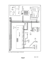
3.3 Power supply
Basically, CPR32-NET is designed for power supply from 230VAC/18VAC transformer with minimal
power output 20VA, but it can also be supplied with 12VDC or 24VDC. The connection of power
supply is shown in fig. 4.
If CPR32-NET network controller is supplied with 18VAC or 24VDC, then 12V backup battery can be
connected in order to provide power supply in case of mains supply shortage.
CPR32-NET charges backup battery with 300 mA stabilized current up to 13.8V. Backup power
supply is activated automatically in case of main powers supply shortage. If the voltage at backup
battery drops below approx. 10V then the battery is automatically disconnected from CPR32-NET
and remains disconnected until mains power supply returns. Depending on charging phase of
backup battery, the voltage at AUX and TML terminals may vary in range of 11V (initial charging
phase) to 13.8V (final charging phase), which is not a symptom of erroneous behaviour but it
results from applied concept of battery charging.


