PowerFlex Digital DC Drive User Manual -
Publication 20P-UM001C-EN-P - July 2008
2-12
Drive Start Up
1. When checking motor polarity, the drive will have power applied
and the motor will rotate. Verify that the motor is uncoupled from
the load. If the motor cannot be uncoupled from the load, the
following motor checks are recommended:
❏
All electrical connections are tight.
❏
The brushes are properly seated.
❏
The motor shaft is free to rotate.
2. Access the “Motor Control” file, “Speed Feedback” group and
verify that Par 414 [Fdbk Device Type] is set to 3 “Armature”
(default).
3. Access the “Speed Command” file, “Discrete Speeds” group and
verify that Par 266 [Jog Speed] is set to the default value (100
RPM) or to an acceptable speed level for this test.
4. If analog input 1 is wired, access the “Analog Inputs” group and
verify that the voltage level is 0V in Par 1404 [Analog In1 Value].
5. While viewing Par 233 [Output Voltage], assert a Jog command
(via the HIM keypad or digital input on the I/O terminal block) and
observe the motor rotation direction. Verify whether or not Par 233
[Output Voltage] is positive.
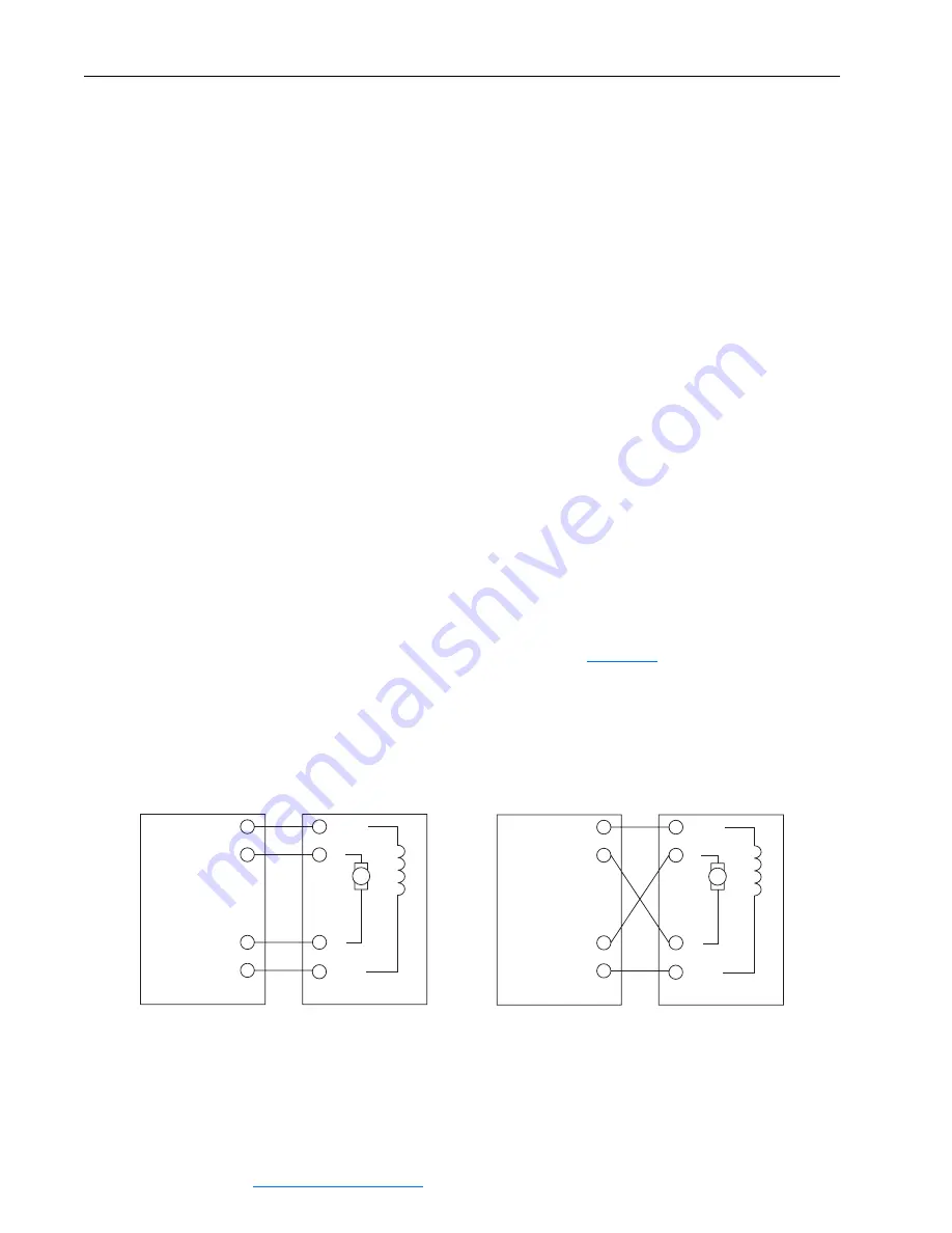
6. If the observed rotation direction is incorrect, remove power from
the drive and continue with step 6 below, while referring to the
motor connection diagrams in
Figure 2.2
below. If the observed
rotation direction is correct, continue with step 10 below.
7. Make certain power is turned off and locked out.
8. Switch the armature leads connected to C (+) and D (-).
Figure 2.2 Motor Connections
C1 (+)
C (+)
D (-)
D1 (-)
PowerFlex DC
Motor
F1 (+)
A1
A2
F2 (-)
(2)
(2)
C1 (+)
C (+)
D (-)
D1 (-)
PowerFlex DC
Motor
F1 (+)
A1
A2
F2 (-)
(2)
(2)
Straight Shunt Machine,
CCW Rotation Facing Commutator End
Straight Shunt Machine,
CW Rotation Facing Commutator End


