PowerFlex Digital DC Drive User Manual -
Publication 20P-UM001C-EN-P - July 2008
Application Notes
C-33
Tuning the Field Current Curve
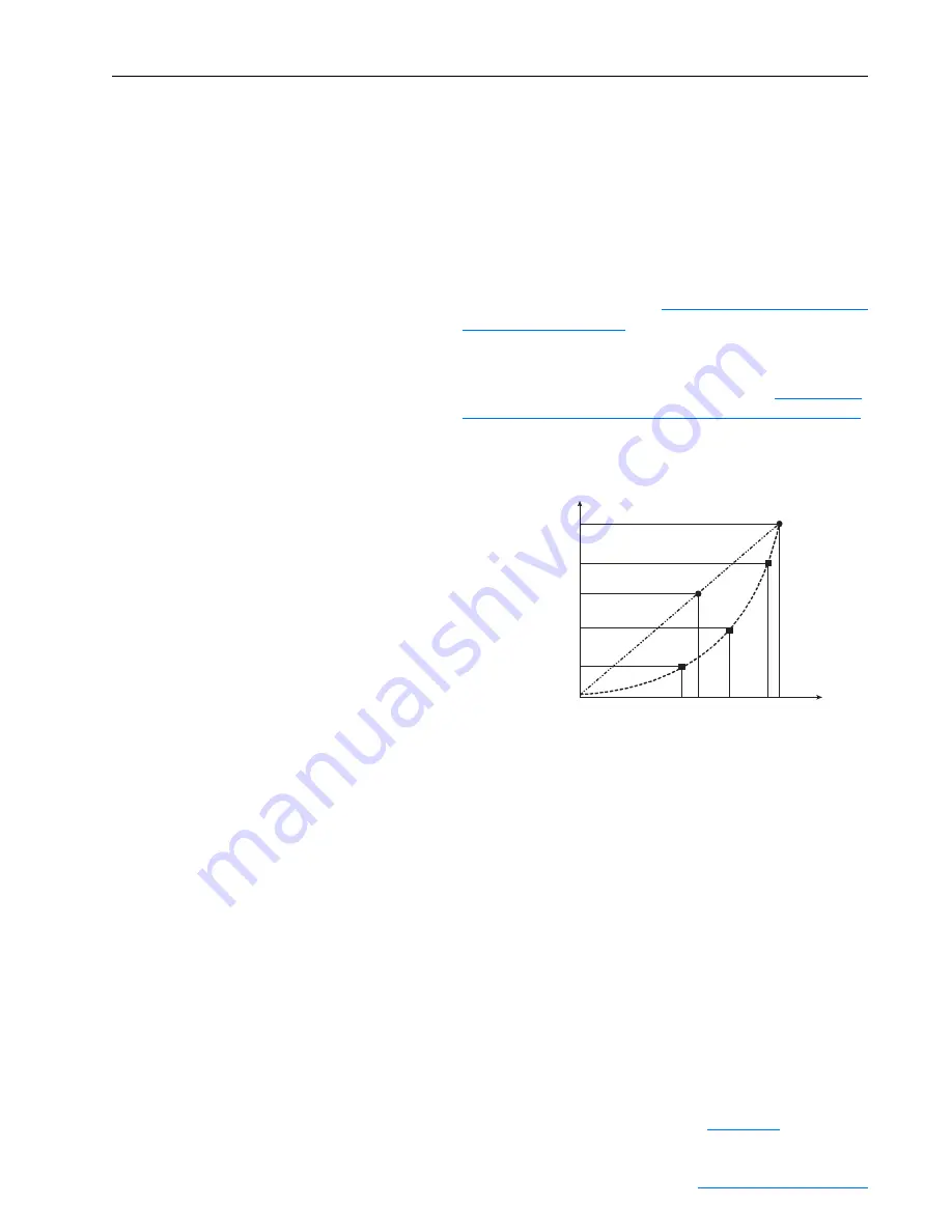
The function of the field current curve is to control the actual motor flux
and, subsequently, motor torque if the field goes into an overvoltage
condition. Figure C.15 below illustrates the relationship between flux and
flux current when the field current curve is defined versus not defined.
Important: Complete the procedures in the order listed below when tuning
the field current curve:
•
Field current regulator. Refer to
.
•
Field current curve tuning (Flux / if curve)
•
Voltage regulator in the field converter. Refer to
the Voltage Regulator in the Field Converter on page C-31
Figure C.15 Curve Conversion Flux/Current
Examples:
•
Curve A - If the default settings of the drive are retained, the flux current
to flux reference will remain linear when the value of Par 500 [Field Ref
Pct] changes. E.g.,
o
If Par 467 [Max Fld Curr Pct] / Par 500 [Field Ref Pct] = 100%,
then Par 234 [Fld Current Pct] / Par 500 [Field Ref Pct] = Par 280
[Nom Mtr Fld Amps]
o
If Par 467 [Max Fld Curr Pct] / Par 500 [Field Ref Pct] = 50%, then
Par 234 [Fld Current Pct] / Par 500 [Field Ref Pct] = 50% of Par
280 [Nom Mtr Fld Amps]
•
Curve B - If the field current curve fine tuning procedure is completed,
the flux current to flux reference curve will follow a curve determined by
the real flux percentage of Par 500 [Field Ref Pct] necessary to
determine the circulation of the field current for the connected system.
Refer to the Current Regulator block diagram on
P
a
r 2
3
4 [Fld C
u
rrent Pct]
P
a
r 2
8
0 [Nom Mtr Fld Amp
s
] @ 100
%
P
a
r 916 [Fld Con
s
t 90 Pct]
P
a
r 2
8
0 [Nom Mtr Fld Amp
s
] @ 50
%
P
a
r 91
8
[Fld Con
s
t 40 Pct]
P
a
r 917 [Fld Con
s
t 70 Pct]
40
%
50
%
70
%
90
%
100
%
C
u
rve A
C
u
rve B
P
a
r 500 [Field Ref Pct]


