Installation and user manual
Error! Use the Home tab to apply
Titolo 1 to the text that you want to
appear here.
11
Figure 11
3.6.1
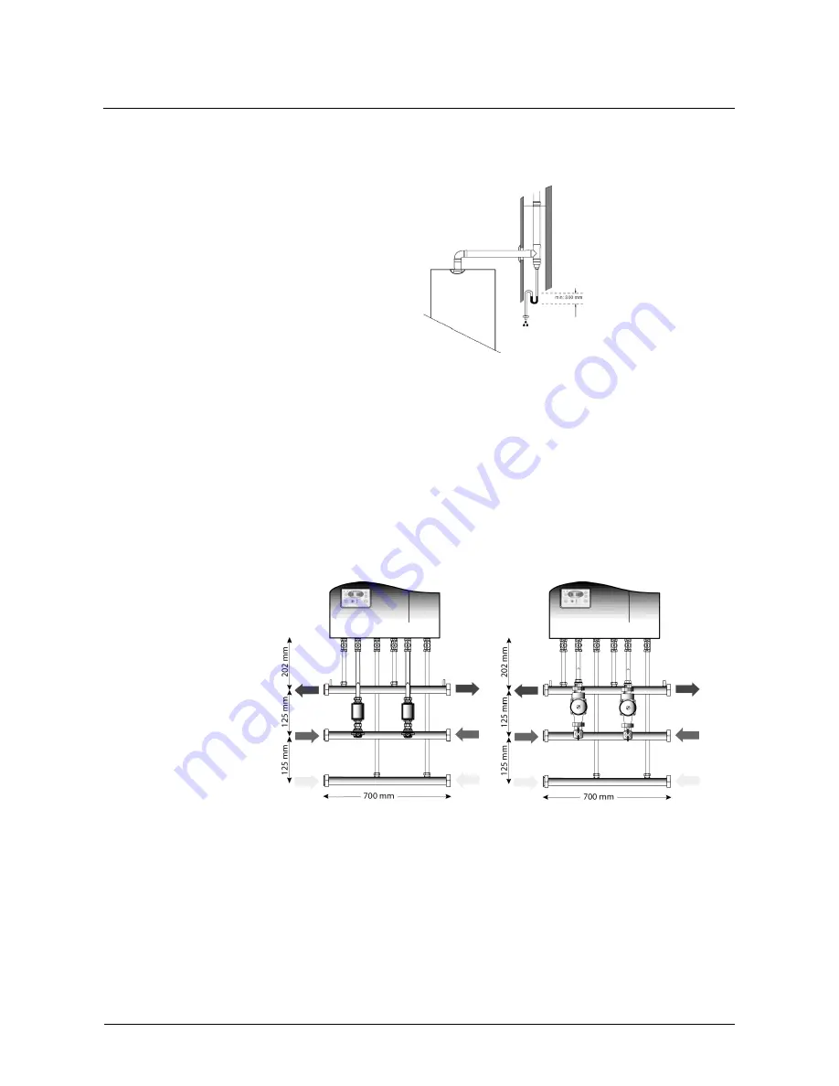
Siphon along the discharge piping
Should it be necessary to extend the vertical or
the horizontal section of the discharge piping to
over 4 metres, create a siphon for condensate
drainage at the foot of the pipe. The siphon's
useful length must be at least 30 cm (see
Figure 12). The siphon discharge shall then be
connected to the sewage system.
Condensate maximum production (50°C-30°C)
100% :
……………………...............14,4 Kg / h
Figure 12
3.7 Hydraulic connection
In Figure 6 at page 7 there are the hydraulic connections for Caldaria Condensing 100. The connection sizes
are:
Gas
3/4”
(G in
Figure 6
)
System delivery
1”
(M in
Figure 6
)
System return
1”
(R in
Figure 6
)
To create the hydraulic connection, two kits are available:
the first one can be used for the installation of one Caldaria Condensing 100;
the second one is designed for the battery installation of maximum four Caldaria Condensing 100 (in this
case the system has a power of 400 kW). It is necessary to complete the connection to the hydraulic set
using a two way valve or a pump (see also par. 4).
In the following pictures is
shown the kit for a Caldaria
Condensing
100
composed by the following
items:
N°1 gas collector Ø45 mm
N°1 delivery collector. Ø45
mm
N°1 Return collector. Ø45
mm
Each collector is fitted with
2 branch pipe, at whose
ends are two 1' taps for
delivery
and
return
collectors, and two ¾' taps
for the gas collector. In
Figure 13
we have a
Figure 13
Figure 14
connection using the two way valve kit and in
Figure 14 a connection using the pump.
Summary of Contents for CALDARIA CONDENSING 100
Page 38: ...Installation and user manual...


