Installation and user manual
Error! Use the Home tab to apply
Titolo 1 to the text that you want to
appear here.
5
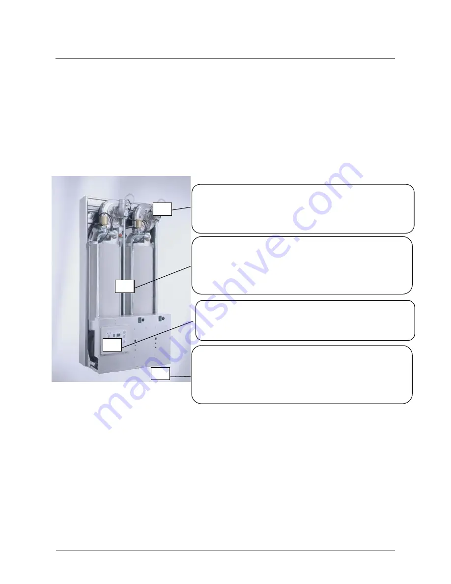
Pre-mixing unit consisting of a modulating gas valve integrated with
a high-head fan. The system ensures a constant mixing ratio in all
operating conditions, and flue gas discharge through a plastic (PP)
exhaust pipe, up to 30 linear metres long.
High-efficiency burnt 50 kW heat exchanger fitted with bi-metal
corrugated internal coil:
water side: copper
flue gas side: stainless steel
The micro-flame burner is located high, at the centre of the
exchanger, and is a grid-type, with one single ignition electrode
Digital control panel. The panel includes several adjustment
functions and is equipped with a double display, which, depending
on the circumstances, shows either the operation status or the
error codes related to the most common failures
The Master/Slaves adjustment system is located behind the front
panel. It consists of a master control unit that manages two Slave-
type control units. Each slave card controls the operation and of
the individual unit to which it is connected. The Master card can
manage up to 60 Slave cards and is set for tele-management,
temperature regulation, and remote control.
Ø 50mm flue gas exhaust for each thermal unit (see fig.
8
)
Flue pipe until 30 meters
Standard condensate discharge system in the boiler
Fast connection of water, condensate and gas (optional) collectors, with right and left outlet
Various thermal modules and the Master control station
Standard outside temperature regulation
Modulating and modular regulation of the power of individual thermal units;
Automatic inversion (adjustable time interval) of the burners' ignition order
Selection of the burner's cascade ignition criterion (power %)
Management of sanitary function and circuits at different temperatures, with or without operation priority;
Important safety devices, like a water differential pressure switch to control flux minimum flux for each unit
2.3 Construction details
Caldaria Condensing 100 thermal assemblies have two thermal units inside the metal cabinet, respectively.
Each thermal unit is connected to the hydraulic system and the gas supply in parallel to the others and
consists of the following main components:
Heat exchanger
Pre-mixing assembly
Control and management slave card
Safety kit
50 mm polypropylene flue gas pipe
Each Caldaria Condensing 100 series may be combined, in series, with other similar generators, to create
modular thermal station where the various thermal units are managed by one single Master card, which can
be installed on any of the thermal assemblies making up the station.
It is necessary to install in each unit a two way valve or a pump. For more information see par. 3.7 and the
section 4.
Figure 3 :Caldaria Condensing 100
1
2
3
4
Summary of Contents for CALDARIA CONDENSING 100
Page 38: ...Installation and user manual...


