No.
3126
3
Bauanleitung, Assembly instructions, Notice de montage
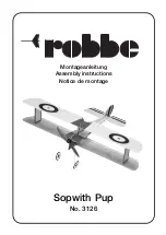
Sopwith Pup
Technische Daten
Spannweite oben:
ca. 720 mm
Spannweite unten:
ca. 720 mm
Gesamtlänge:
ca. 565 mm
Gesamtflächeninhalt:
ca. 22 dm
2
Fluggewicht:
ca. 160 g
Gesamtflächenbelastung:
ca. 7,3 g/dm
2
Allgemeine Hinweise für den Bauablauf
Der Zusammenbau des Modells erfolgt nach den einzelnen Zeichnungen.
Textlich wird nur auf Punkte hingewiesen, die besonders zu beachten
sind.
Klebearbeiten an Depron® Teilen nur mit Foam-Speed oder Epoxy aus-
führen. Foam-Speed sparsam verwenden, da herunter laufende Tropfen
die Farbe anlösen können.
Zur Befestigung der Ruder sowie für einige Verstärkungen Tesafilm ver-
wenden.
Um glatte Schnitte zu erreichen, ein scharfes Modellbaumesser benut-
zen.
Als Fernsteuerung benötigen Sie eine Anlage ab 4 Kanälen und 3 Servos
sowie einen elektronischen Flugregler.
Die Ruderausschläge für Fliegen auf engem Raum so groß wie möglich
wählen. Es empfiehlt sich, 35 - 40 % Expo einzumischen.
Hinweise zur Motorisierung
In das Modell kann ein Brushlessmotor (Außenläufer) für Direktantrieb
eingebaut werden.
Vor Baubeginn den Motor mit entsprechendem Regler auswählen. Reg-
ler und Flugakku mit geeigneten Steck-Kontakten versehen.
Nicht enthaltenes, jedoch erforderliches Zubehör
Stück
Bezeichnung
Bestell Nr.
3
Servos FS 31 Pico
8449
1
Roxxy BL-Outrunner 2815
4777
1
Regler Roxxy Control BL 808
8621
1
Lipoly Akku 2S1P 7,4 V 350 mAh
4808
1
Luftschraube APC Slow Fly 9x3,8”
77880904
Ladegeräte für Lipoly Akkus, Ladekabel, Werkzeuge und Hilfsmittel
siehe robbe-Hauptkatalog.
Geeignete Klebstoffe
robbe ropoxy,
5066
robbe-Foam Speed
5069
Aktivatorspray
5017
Specification
Top wingspan:
approx. 720 mm
Bottom wingspan:
approx. 720 mm
Overall length:
approx. 565 mm
Total surface area:
approx. 22 dm
2
All-up weight:
approx. 160 g
Total surface area loading:
approx. 7.3 g / dm
2
Sequence of assembly
The model should be assembled as shown in the individual drawings.
The text only points out areas of particular importance.
Depron® parts should be glued using Foam-Speed (foam-safe cyano-
acrylate) or epoxy exclusively. Use Foam-Speed sparingly, as excess
adhesive may run onto the coloured areas and dissolve the paint.
Tesafilm (clear adhesive tape) is used to attach the control surfaces and
for various reinforcements.
Use a very sharp modelling knife to obtain clean cuts in the foam mate-
rial.
For this model you require at least a four-channel radio control system,
together with three servos and an electronic speed controller.
The control surface travels for flying in a confined space should be as
large as possible. We recommend that you apply 35 - 40% Expo to the
flying controls.
Power system
A direct-drive brushless out-runner motor can be installed in the Flyball.
Select a suitable motor and speed controller before you start building
the model, and fit suitable connectors to both items.
Essential items not included in the kit
No. off
Description
Order No.
3
FS 31 Pico servo
8449
1
Roxxy 2815 BL out-runner motor
4777
1
Roxxy Control BL 808 speed controller
8621
1
Li-Poly battery, 2S1P 7.4 V / 350 mAh
4808
1
APC Slow Fly 9 x 3.8” propeller
77880904
See the main robbe catalogue for details of chargers for Li-Poly batte-
ries, charge leads, tools and aids to building.
Adhesives
robbe ropoxy
5066
robbe Foam Speed
5069
Activator spray
5017
Caractéristiques techniques
Envergure de l’aile du haut :
approx. 720 mm
Envergure de l’aile du bas :
approx. 720 mm
Longueur totale :
approx. 565 mm
Surface alaire totale :
approx. 22 dm
2
Poids en ordre de vol :
approx. 160 g
Charge alaire à la surface totale :
approx. 7,3 g/dm
2
Consignes générales concernant la construction
Assembler le modèle selon les indications de la séquence des schémas.
Le texte ne fait référence qu’à des points particuliers de l’assemblage
auxquels il faut être attentif.
N’effectuer les collages sur les éléments en Depron® qu’avec le produit
spécifique Foam-Speed ou de la colle époxy.
Appliquer le produit Foam-Speed parcimonieusement car les gouttes ris-
quent de dissoudre la peinture.
Pour fixer les gouvernes et effectuer certains renforts utiliser des morce-
aux de ruban adhésif.
Pour obtenir des découpes parfaitement nettes, utiliser un couteau de
modélisme bien aiguisé.
Pour piloter l’appareil, il faut disposer d’un ensemble de radiocommande
à partir de quatre voies avec trois servos, de même que d’un variateur
de vitesse électronique.
Pour voler dans les espaces réduits, sélectionner des débattements de
gouverne aussi grands que possibles. Il est recommandé d’y mixer de
35 à 40 % d’exponentiel.
Consignes concernant la motorisation
I
l est possible de monter dans le modèle un moteur sans balais (à induit
externe) pour une transmission directe.
Avant d’installer le moteur il est impératif de disposer du variateur appro-
prié. Munir le variateur et l’accu d’entraînement des connecteurs appro-
priés.
Accessoires non contenus dans la boîte de construction mais indis-
pensables à la mise en œuvre du modèle
Nbre
désignation
réf.
3
servos FS 31 Pico
8449
1
moteur sans balais à induit externe Roxxy
2815 4777
1
variateur sans balais Roxxy
808 8621
1
accu Lipoly 2S1P 7,4 V 350 mAh
4808
1
hélice vol lent APC Slow Fly 9x3,8”
77880904
Chargeurs pour accus Lipoly, cordon de charge, outillage et acces-
soires, cf. catalogue général robbe.
Colles appropriées
robbe ropoxy, 5066
mousse robbe-Foam Speed
5069
activateur en bombe Aktivatorspray
5017


