MH TH
Pag. 19
REV. 08 11/07
UK
voltage corresponds to the voltage stated on the machine label. The permitted tolerance is
±
10%
of rated voltage. When sizing the differential thermomagnetic switch, take into account the
electrical input values stated on the label.
•
Important note: the thermomagnetic switch must be placed next to the machine so as to be easily
seen and reached by a technician in case of maintenance.
•
The section of the power supply cable must be adequate for the power absorbed by the machine,
which is stated on the relevant label fixed to the machine itself.
•
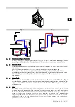
The law requires that the unit be earthed; therefore, it is necessary to connect it to an efficient
earthing system.
No liability whatsoever can be accepted in the event of failure to comply with this
requirement or if the electrical system to which the machine is connected does not comply with the
regulations in force.
•
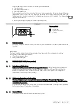
For machines with three-phase electrical power, it is necessary to check the rotation direction of
the motor fans. If it does not correspond to the one shown by the arrow on the label placed near
the fans, it is necessary to switch off the machine and invert two phases of the mains; it is then
possible to re-start the machine.
•
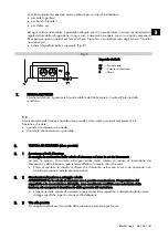
A mechanical thermostat set at 40°C must be fitted to the evaporator; this will deactivate the
heaters in case of overheating. The thermostat bulb must be placed in the fin assembly in the
highest position inside the evaporator.
Important note: Scroll compressors compress only in one rotation direction. However, three phase
compressors will rotate in both directions depending upon the phase connections to T, T2 and T3
terminals. Since there is a 50% possibility of connecting them so that they rotate in the reverse
direction, it is very important to check the correct rotation direction. This is checked by monitoring
the drop in suction pressure and the rise in discharge pressure when the compressor is started.
Reverse rotation will produce a sound level that is higher than the one produced by the correct
rotation direction and an electrical input that is higher than that quoted in the catalogue. We advise
you to fit a protection device for inverse phases, which will operate if the phases are not correctly
connected.
6.
TECHNICAL DATA
All MH-TH condensing units are supplied in nitrogen pressure. They are provided with safety
pressure switches with fixe setting and automatic reset on the HBP line, and with adjustable setting
and automatic reset on the LBP line.
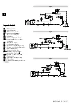
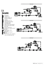
The refrigerating diagram of a condensing unit with air-cooled condensation has been included here
below:
•
Drawing 5: refrigerating diagram with scroll compressor and liquid injection valve (DTC)
•
Drawing 6: refrigerating diagram with scroll compressor and capillary injection
•
Drawing 7: refrigerating diagram with scroll or reciprocating compressor
Important note: Refrigerating diagrams of non-standard units will be supplied separately.
Summary of Contents for MH-HT
Page 2: ...MH TH Pag 2 REV 08 11 07 ...
Page 67: ...MH TH Pag 67 REV 08 11 07 ...
Page 69: ...MH TH Pag 69 REV 08 11 07 ...
Page 70: ...MH TH Pag 70 REV 08 11 07 ...
Page 71: ......

