background image

9 Appendixes 


46 

Rittal Perforex BC machining centre 

EN 

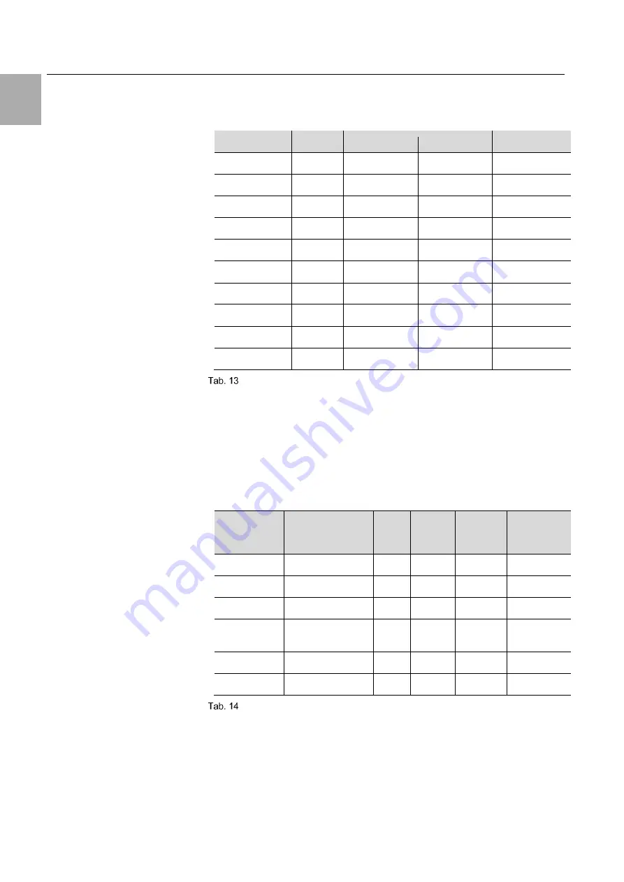
9.2  Drill 

Drill in OEM quality for Perforex BC machining centres. Suitable for all Per-
forex types. 


Suitable for BC 

Type 

Ø [mm] 

Packs of 

Model No. 

All 

2.6 

10 

4050.801 

All 

3.3 

10 

4050.802 

All 

4.2 

10 

4050.803 

All 

5.0 

10 

4050.804 

All 

6.0 

10 

4050.805 

All 

6.8 

10 

4050.806 

All 

8.5 

10 

4050.807 

All 

S-k 

8.5 

4050.808 

All 

10.5 

4050.809 

All 

S-k 

10.5 

4050.810 

:  Drill 

Identification type: 

= Twist drill 

S-k  = Short twist drill 
 

9.3  Milling cutter 

Milling cutter in OEM quality for your Perforex BC machining centre. Recom-
mendation: Milling cutter types in accordance with recommended material 
that should be milled. 


Suitable for 
BC 
 

Workpiece  
material 

Type 

Ø [mm] 

Packs of 

Model No. 

All 

Steel 

6.0 

10 

4050.818 

All 

Steel 

6.0 

4050.891 

All 

Stainless steel 

PM 

4.0 

4050.885 

All 

Steel / stainless 
steel 

P+ 

6.0 

4050.620 

All 

Aluminium/plastic 

6.0 

4050.819 

All 

Aluminium/plastic 

4.0 

4050.820 

:  Milling cutter 

Identification type: 

= Standard milling cutter 

= Performance milling cutter 

PM  = PM milling cutter 
P+  = Perf milling cutter 

= Airline 


Summary of Contents for 4050.101

Page 1: ...Perforex BC machining centre 4050 101 4050 108 4050 107 4050 230 Operating instructions ...

Page 2: ...ccess Yours Rittal GmbH Co KG Rittal GmbH Co KG Auf dem Stuetzelberg 35745 Herborn Germany Tel 49 0 2772 505 0 Fax 49 0 2772 505 2319 E mail info rittal com www rittal com Sales ras info rittal de 49 0 2772 505 2562 or 2077 Service service rittal de 49 0 2772 505 1855 We are always happy to answer any technical questions regarding our entire range of products ...

Page 3: ...ustment optional 19 3 1 12 Automatic tool breakage check 19 3 1 13 Brush strips Performance package optional 19 3 1 14 Tool mounting aid accessory 20 3 1 15 Minimal lubrication 21 3 2 Proper use foreseeable misuse 21 3 2 1 Proper materials 22 3 2 2 Non intended use 22 3 3 Dimensions and clearances 22 3 4 Scope of supply 23 4 Operation 24 4 1 Description of operating and display elements 24 4 1 1 M...

Page 4: ...ons 39 7 1 Machine data overview 39 7 1 1 Noise emissions 39 7 2 Available machine options 41 7 3 Available accessories 42 8 Spare parts 43 8 1 Consumables 44 9 Appendixes 45 9 1 Support bolts 45 9 2 Drill 46 9 3 Milling cutter 46 9 4 Thread tap cutter 47 9 5 Perforex BC 1001 HS top view 48 9 6 Perforex BC 1007 HS with motorised depth adjustment 1600 mm top view 49 9 7 Perforex BC 1007 HS with mot...

Page 5: ...ne and must always be at hand and available for the operating and maintenance personnel at all times 1 3 Symbols in these operating instructions The following symbols are used in this documentation Danger Hazardous situation which will result in death or serious in jury if the instructions are not followed Warning Hazardous situation which may lead to death or serious in jury if the instructions a...

Page 6: ...mentary sheets of the components modifications and additional equipment used such as Workshop Programming Brush strips all Tool mounting aid all Clamping frame all Busbar clamper all Motorised depth adjustment all except BC 1001 HS Clamping height extension BC 1008 HS Depth adjustment extension BC 1007 HS Comfort clamping BC 2014 HS 1 5 Normative references The Perforex BC machining center is buil...

Page 7: ...son involved with the operation or maintenance of the Perforex BC machining centre must have read and understood the complete operat ing instructions The switch off procedures stated in these operating instructions must be observed Refrain from any operation that could impair the safety of the operator and the Perforex BC machining centre Unauthorized modifications and changes that could impair th...

Page 8: ...n or national legislators as well as the regulations for accident prevention and environmental protection valid for your country Warning Hazardous situation which may lead to death or serious in jury if the instructions are not followed In the DGUV German Social Accident Insurance area of validity the op erating company is obliged to check every 6 months the proper condition in accordance with DGU...

Page 9: ... centre Despite the inherent safe design the safety precautions and the supplemen tary protective measures residual dangers remain In particular the following situations require increased attention by the oper ator The machining of workpieces that do not conform to the proper use see section 3 2 Proper use foreseeable misuse The machine can normally be operated by one person If the machine should ...

Page 10: ...ration involves loading the table as well as working on the operator console on the left hand side For maintenance work the maintenance personnel also temporarily occupy only those areas marked with W The gantry can be moved to the side for maintenance in the de energised state This facilitates easy access to all maintenance points 2 7 Safety equipment and warning notes Danger Non functioning safe...

Page 11: ...ical user interface remain switched on Light array light barrier A light array light barrier is provided to protect the work area during the ma chining operation The transmitter Fig 2 item 3 and receiver Fig 2 item 4 of the light array light barrier are located on the side wings of the safety fence that encloses the work area The voltage supply for all outlets is interrupted if this area is entere...

Page 12: ...2 item 5 Note Further warning signs are placed on the installed supplementary components Observe the associated documentation in particu lar the safety instructions for these components as well as their operating instructions The correct functioning of the safety equipment must be checked at least weekly ...

Page 13: ...solver evaluation of 1024 pulses per motor revolution that are transferred via the servo converter to the controller To ensure a long service life of the pinion and the gear rack they are sprayed with an oil air mixture from a nozzle when they move blowing noise For this purpose a separate gear rack oiler is used A thin oil film is visible on the gear rack when the setting is correct The above men...

Page 14: ...ed on the left hand operating side as well as in the lower area After placing the part the mechanical clamping brackets Fig 8 are applied and clamped The spacer bolts are placed in the envisaged drill holes of the machine table as appropriate for the part size 3 1 3 Enclosure The enclosure contains all controllers and drives required for operation The machine main switch is located here The enclos...

Page 15: ...ning from here Fig 5 Operating element details 3 1 5 Light array The light array serves as safety equipment and interrupts the running pro gram when the safety loop is interrupted For more detailed information re fer to section 2 7 Safety equipment and warning notes 3 1 6 Tool change magazine The tools are stored in the plastic tool holders in the gripper groove Fig 6 A push button on the cross sl...

Page 16: ... Tools in the tool change magazine 3 1 7 Pneumatic clamping device The pneumatic clamping device consists of the pneumatic clamping strip for panels and cubes at the component support for Y 0 as well as also the pneumatic clamping for cubes via clamping cushions at the traverse Fig 9 The clamping devices are actuated via push buttons on the left and right hand side of the machining area Fig 7 Pneu...

Page 17: ...nical clamping brackets Caution Risk of being crushed Fingers might be crushed when applying the clamping brack ets 3 1 9 Cube machining The cube clamping is located on the right hand side of the machine The cube is placed here and then traversed to the rear either manually or option ally with motorised support The cube is then clamped using the pneumatic clamping device Fig 9 Cube clamping 3 1 10...

Page 18: ...ated at the top of the gantry Fig 10 Cross slide of a Perforex BC 1008 HS To prevent the cross slide from falling down when the controller is switched off the drive motor has a holding brake that keeps the cross slide reliably in position even when de energised Spindle Z support The spindle is fastened to the cross slide and moves on this forwards and backwards in the Z direction The spindle drive...

Page 19: ...h on the machine To do this a motor driven slide is traversed backwards against the component in the clamping position when the push button is actuated 3 1 12 Automatic tool breakage check The tool is checked after each work step and before storing the tool in the tool magazine This ensures that work steps are performed only with cor rectly functioning tools The automatic tool breakage check is lo...

Page 20: ...ol mounting aid accessory The tool mounting aid is located at the outer left hand side on the machine frame or can be retrofitted there The tool mounting aid contains not only a retainer and locking mechanism for the tool holders but also a scale with which the length of the tool can be read directly during change over or the tool can be adjusted easily to the dimension stored in the machine progr...

Page 21: ...heets must be produced from a material typically used in enclosure con struction see section 3 2 1 Proper materials and for cubes may be ma chined only from the outer side Your Perforex BC machining centre is designed as an individual workplace Any other use is deemed improper Your Perforex BC machining centre is state of the art and built according to recognised safety regulations Nevertheless im...

Page 22: ...al 3 2 1 Proper materials Your Perforex BC machining centre is able to machine the following machin able materials and wall thicknesses Material Standard wall thickness up to mm Optional wall thickness up to mm Steel 3 5 Stainless steel 3 5 Copper 3 10 Aluminium 3 10 Plastic 3 10 Proper materials Other materials and wall thicknesses are deemed improper If other materi als need to be machined the m...

Page 23: ... its type your Perforex BC machining centre is delivered in one packaging unit BC 1001 1007 HS or in two packaging units BC 1008 2014 HS incl all auxiliary equipment Check the packaging carefully for signs of damage Any packaging damage may be the cause of a subsequent functional failure Check your Perforex BC machining centre for transport damage Note Damage or other defects such as incomplete de...

Page 24: ...witch is located on the machine enclosure and switches the main operating voltage on or off 4 1 2 Operating element Fig 15 Perforex BC operating element The operating element includes an industrial PC and is connected directly to the machine controller Programs are created called and modified here The operating element also contains all push buttons switches and control ele ments in order to relea...

Page 25: ... used as thrust bearing for the clamping force Ideally they should be positioned directly op posite or at least near the applied force 4 1 4 Push button for pneumatic clamping strip Fig 17 Push button for pneumatic clamping strip The actuator of the pneumatic clamping strip is located at the left hand side next to the tool magazine This clamping strip clamps the workpiece lower edge fatigue free a...

Page 26: ...hining A manual quick release fastener for fastening the machine door is located at the top and bottom of the machine door This makes it possible to machine large panels with closed machine door or as necessary to machine cubes with opened door To open the machine door release both quick release fasteners and swivel the door into the machine Hold the door when opening so that it closes smoothly ag...

Page 27: ...control voltage as well as servo controller On The illuminated push buttons now illuminate and the axis drives are in closed loop control The axes can now be homed in accordance with the in structions Note The safety area is activated when the machine becomes opera tional The EMERGENCY STOP status is activated immediately when the safety area is entered This must be prevented in par ticular for ca...

Page 28: ...software can be found in the description of the Workshop programming software see sec tion 1 4 Associated documents 4 2 5 Panel machining 1 Place the appropriate workpiece 2 Push the workpiece against the side limit stops 3 Clamp the workpiece at the top and bottom 4 Start the desired program 5 The machining begins 6 After completion of the machining program the support travels to the programmed w...

Page 29: ...hop programming operating in structions at our internet homepage 4 2 8 Replacing worn tools Once a tool is worn replace it to ensure a perfect cutting pattern and to mini mise standstill times 1 Remove the tool holder with the broken or worn tool from the spindle 2 Clamp the tool holder in the tool mounting aid or some other suitable clamping tool 3 Loosen the screw joint at the tool holder to rel...

Page 30: ...g 20 item 7 Setting of the secondary air quantity via the throttle valve screw mounted on the side Fig 20 item 3 Filling The M K Basis must be refilled when the Minimum marking in the filling level display Fig 20 item 5 is reached The minimal lubrication system may be filled only in the pressure free state To do this interrupt the air supply Fig 20 item 1 that supplies the minimal lubrication syst...

Page 31: ... during flooding On Off several times with the magnetic valve optionally manual slide valve Fig 20 item 2 to flush air and air bubbles from the capillary hose 8 Close the internal spindle again when bubble free oil exits at the nozzle see Fig 20 9 Mount and tighten the rotary knob Fig 20 item 7 10 Operational device 4 3 Error messages 4 3 1 Troubleshooting Proceed in a systematic and targeted way ...

Page 32: ...a new hard disk and reload the machine data Warning Incorrect machine data can cause unexpected functions on the machine Programming tasks in the machine base pro gram may be performed only by trained specialists To backup the settings of your machine at handover a system recovery file was created during the commissioning This is on a USB stick normally re tained in the housing of the industrial P...

Page 33: ...ipment triggered Switch off the controller and restart Program does not start the controller can no longer be switched on X Y or Z axis at the limit position Move the appropriate axis in manual operation from the limit position Closed loop controllers not ready Safety area is not free Make safety area free Entered traversal path too large Correction of the soft ware limit position No pressure Only...

Page 34: ...ed to their original position and acti vated if necessary before the renewed commissioning of the machine 6 2 Inspection In regular intervals for safety reasons or otherwise the machine must be subjected to a thorough inspection by an appropriately trained specialist Check the safety of the electrical system in particular the cable insulation Check the state of the power supply cable and the motor...

Page 35: ...otective equip ment in particular protective gloves Remove swarf from the machine in particular in the area of functional parts such as gear racks linear guides pressure fixture pressure rollers and swarf extraction Clean the motor ventilator hoods in order to achieve optimum motor cool ing Inspect the filter elements of the ventilation units in the enclosure weekly and replace them if necessary R...

Page 36: ...t X Gear rack drive X Tool holder X Enclosure cooling filter X Swarf extraction filter bag X Cleaning Machine in general X Gear racks X Linear guides X Pressure fixture incl pressure rollers X Swarf container on spindle X Tool holder X Sinter filter of the maintenance unit X Light array X Hollow shaft X Lubrication X Y Z axis linear guides X 2 see section 6 4 2 Gear racks 1 see section 6 4 2 Cuboi...

Page 37: ...s for the BC 1007 with motorised depth adjust ment as example Legend 1 X axis gear racks and toothed wheel 2 Y axis gear racks and toothed wheel 3 Z axis gear racks and toothed wheel 4 Tool 5 Electrospindle bearing assembly 6 X axis linear guides 4x 7 Y axis linear guides 4x 8 Z axis linear guides 4x 9 Enclosure filter elements 2x 10 Pressure unit gear racks and toothed wheel 11 Pressure unit line...

Page 38: ...enetrating oil Lubricant recommendations 6 5 Software updates Your Perforex BC machining centre does not generally require any updates in order to retain its performance If necessary request the current software release If you then consider an update make a request to our service department with details of the machine number and the year of manufacture from the rating plate Depending on the instal...

Page 39: ...60 x 1 500 x 5 Maximum feed rate mm min 3 000 3 000 3 000 3 000 Typical feed rate in series oper ation Performance mm min 900 900 900 900 Max spindle speed RPM 21 000 21 000 21 000 21 000 Max spindle power kW 11 11 11 11 Axis speed X axis mm min 60 000 60 000 60 000 60 000 Axis speed Y axis mm min 60 000 60 000 60 000 60 000 Axis speed Z axis mm min 12 000 20 000 20 000 20 000 Tool magazine size 1...

Page 40: ...ine whether further previsions may be required Factors that can affect the current workplace value contain the duration of the effect the characteristic of the workspace other noise sources other machines and other neighbouring effects In any case the permitted workplace values can vary from country to country This information however should allow the user to better assess the danger and risk The ...

Page 41: ...performed at the factory The following machine options are available for selection Option BC 1001 HS BC 1007 HS BC 1008 HS BC 2014 HS Additional zero points X X X X Extended depth adjustment X Motorised depth adjustment X Clamping height extension X Comfort clamping X Additional machine door X Machine options Because the motorised depth adjustment belongs to the standard variant for types BC 1008 ...

Page 42: ...er X X X X Circular thread milling tool X X X X Aluminium plastic milling tool set X X X X Machine thread tap cutter set X X X X SK30 tool holders X X X X Collets for drills and thread tap cutters X X X X Milling cutter extender X X X X Holder for minimal lubrication for the milling cut ter extender X X X X Deburrer incl spare blades X X X X Side cutter X X X X Magnetic rod X X X X Grease gun X X ...

Page 43: ...fic spare part send us a photo of the defective part to gether with a description as well as the machine number on the machine rating plate Note Only with original spare parts and competent installation can we ensure long term correct operation Consumables can be found in the following section ...

Page 44: ... kg 4050 863 Special oil for gear racks 1 l 4050 862 All side roller for pressure plate 4 4050 859 Rubber ring for pressure plate 1 4050 864 Plastic hose for swarf extraction 13 m 4050 874 Clamping finger for front clamping unit 1 4050 878 Support bolts See 9 1 Drill See 0 Milling cutter See 9 3 Thread tap cutter See 0 Circular thread milling tool 1 4050 887 White touch up pen RAL 9003 1 4050 090 ...

Page 45: ...arked with X Length mm Type Packs of Model No BC 1001 HS BC 1007 HS BC 1008 HS BC 2014 HS 33 I 10 4050 849 X 54 I 10 4050 847 X 57 I 10 4050 843 X X 78 I 10 4050 842 X X 73 V 1 4050 845 X X X 69 S 10 4050 846 X X 73 S 10 4050 844 X X X 90 S 10 4050 841 X X Support bolts identification Identification type I Internal thread V Adjustable S Pluggable ...

Page 46: ...S Twist drill S k Short twist drill 9 3 Milling cutter Milling cutter in OEM quality for your Perforex BC machining centre Recom mendation Milling cutter types in accordance with recommended material that should be milled Suitable for BC Workpiece material Type Ø mm Packs of Model No All Steel S 6 0 10 4050 818 All Steel P 6 0 5 4050 891 All Stainless steel PM 4 0 5 4050 885 All Steel stainless st...

Page 47: ... your Perforex BC machining centre Suitable for Workpiece material Size Packs of Model No Info All All M3 3 4050 811 All All M4 3 4050 812 All All M5 3 4050 813 All All M6 3 4050 814 All All M8 3 4050 815 All All M10 3 4050 816 All All M12 3 4050 817 All All M12 1 4050 887 Circular thread milling cutter Thread tap cutter ...

Page 48: ... to make technical modifications details without guaran tee Fig 22 Perforex BC 1001 HS top view with dimensions Legend 1 Enclosure with power and network connection from below 2 Air connection 3 Operator console for screw mounting on the floor in the specified separation 4 Light array A X axis traversal path ...

Page 49: ...ght to make technical modifications details without guaran tee Fig 23 Perforex BC 1007 HS top view motorised depth adjustment 1600 mm with dimensions Legend 1 Enclosure with power and network connection from below 2 Air connection 3 Operator console for screw mounting on the floor in the specified separation 4 Light array A X axis traversal path ...

Page 50: ...ght to make technical modifications details without guaran tee Fig 24 Perforex BC 1007 HS top view motorised depth adjustment 2000 mm with dimensions Legend 1 Enclosure with power and network connection from below 2 Air connection 3 Operator console for screw mounting on the floor in the specified separation 4 Light array A X axis traversal path ...

Page 51: ...difications details without guaran tee Fig 25 Perforex BC 1008 HS top view with dimensions Legend 1 Enclosure with power and network connection from below 2 Air connection 3 Operator console for screw mounting on the floor in the specified separation 4 Light array A X axis traversal path B Fixed limit stop C Swivelable limit stop ...

Page 52: ...without guaran tee Fig 26 Perforex BC 2014 HS single door top view with dimensions External dimen sions for two door version identical Legend 1 Enclosure with power and network connection from below 2 Air connection 3 Operator console for screw mounting on the floor in the specified separation 4 Light array A X axis traversal path B Insertable depth ...

Page 53: ...tion by third parties during the warranty period re leases the manufacturer from its warranty obligations 11 Customer service addresses For technical questions please contact our technical support Phone 49 0 2772 505 9052 E mail mailto info rittal com Homepage www rittal com For sales or service enquiries please contact your local Rittal organisa tion Which that is you find at http www rittal com ...

Page 54: ...Notes 54 Rittal Perforex BC machining centre EN ...

Page 55: ...ftware Services You can find the contact details of all Rittal companies throughout the world here www rittal com contact RITTAL GmbH Co KG Auf dem Stuetzelberg 35745 Herborn Germany Phone 49 2772 505 0 E mail info rittal de www rittal com 02 2020 D 100 00000211 01 EN ...

Reviews: