background image

148 

ProSYS Installation and Programming Manual


Report Codes: Disarm Codes 

Quick Keys 

Parameter 

Default


66


77


22


Keyswitch Disarmed 


00


Code to report system disarm via a keyswitch. 

NOTE:

No specific user identification is possible.


66


77


33


Auto Disarmed 

00


Report Code used when the system is Auto Disarmed by a previously 
scheduled event. 

NOTE:

No specific user identification is possible. Refer to the 

ProSYS User's Manual

 for 

additional details.


66


77


44


Remote Disarmed   

00


Report Code for Remote Disarming by the 

MS

 using its Upload/Download


software. 

66


77


55


Wireless Button Disarmed 

00


Code to report disarming with this device. 

66


88


Report Codes: Miscellaneous 

The Miscellaneous menu contains codes that enable the reporting of miscellaneous events to 
the MS. 


To access the Miscellaneous menu: 

1


Access the Report Codes menu, as described on page 137. 

2


From the Report Codes menu, press 

[8]

 to access the Miscellaneous menu options. 

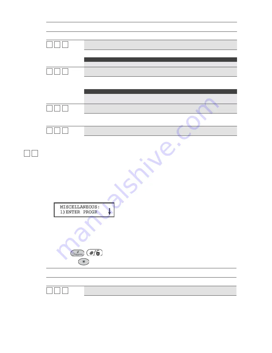
The following display appears: 


3


Access and configure the parameters in the Miscellaneous menu, shown in the table 
below, as follows: 

O

 Press the number of the event to be programmed, meaning enter programming, call 

back request, and so on. 

O

 Enter the 2-digit code representing the event. 

O

 Press 

O

 Press the 

 key to return to the previous programming level. 

Report Codes: Miscellaneous 

Quick Keys 

Parameter 

Default


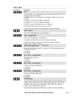
66


88


11


Enter Programming 


00


Report Code for entering the Installer Programming mode, either locally (via 
the LCD keypad) or remotely (via the Upload/Download software). 

Summary of Contents for ProSYS 128

Page 1: ...Installation and Programming Manual ProSYS version 7 xx ...

Page 2: ...e essential requirements and other relevant provisions of Directive 1999 5 EC For the CE Declaration of Conformity please refer to our website www riscogroup com Compliance Statement Hereby RISCO Group declares that the ProSYS series of control panels and accessories are suitable for use in systems designed to comply with EN50131 Grade 3 Environmental Class II EN50136 Series GSM LAN ATS 5 PSTN ATS...

Page 3: ... STEP 5 APPLYING POWER 35 CHAPTER 4 PROGRAMMING THE PROSYS 36 USING THE PROSYS MAIN PANEL PROGRAMMING OPTIONS 36 USING THE LCD KEYPAD 37 PROGRAMMING FROM THE LCD KEYPAD 38 CHAPTER 5 USING THE INSTALLER PROGRAMMING MENUS 45 INSTALLER PROGRAMMING MENU CONVENTIONS 45 SYSTEM 46 ZONES 62 UTILITY OUTPUT 93 CODE MAINTENANCE 103 DIALER 110 REPORT CODES 137 ACCESSORIES 154 MISCELLANEOUS 171 ACCESS CONTROL ...

Page 4: ...ONNECTING THE J10 CONNECTOR 25 FIGURE 9 GROUNDING THE METAL BOX 26 FIGURE 10 GROUNDING THE METAL BOX DOOR 26 FIGURE 11 DIP SWITCH SETTINGS 29 FIGURE 12 KEYPAD INSTALLATION FRONT VIEW 30 FIGURE 13 8 ZONE EXPANSION MODULE 31 FIGURE 14 16 ZONE EXPANSION MODULE 31 FIGURE 15 UTILITY OUTPUT MODULE UO4 SHOWING AN EXAMPLE OF UO4 WIRING 32 FIGURE 16 UTILITY OUTPUT MODULE E08 32 FIGURE 17 UTILITY OUTPUT MOD...

Page 5: ... Communication Modules ACM for IP communication Advanced GSM GPRS modules AGM for advanced cellular communication all in one box and an IP GSM Receiver package for Monitoring Stations MS Additional accessories include integrated Access Control Interactive Voice Module 868 433 MHz Wireless expansion Bus detectors providing Remote Control Diagnostics Program Transfer Module Printer adaptors for para...

Page 6: ...y ETL The system is listed to the following standards Central Station Burglar Alarm Units ANSI UL 1610 Digital Alarm Communicator System Units ANSI UL1635 Police Station Connected Burglar Alarm Units and Systems ANSI UL365 Household Fire Warning System Units ANSI UL985 Proprietary Burglar Alarm Units and Systems ANSI UL1076 Household Burglar Alarm System Units ANSI UL 1023 Preliminary Standard for...

Page 7: ...ndicated wire size or larger numerically lower size In Feet In Meters 22 20 18 16 14 Up to 15 feet Up to 5 meters 15 25 feet 5 8 meters 25 40 feet 8 12 meters 40 60 feet 12 20 meters 60 100 feet 20 30 meters Table A 2 Wiring Between the ProSYS Main Panel and the 16 5 VAC 40VA Plug In Transformer Wire Gauge Max Combined Length of ALL Expansion BUS Wiring 24 AWG 7 02mm 150 meters 492 feet 22 AWG 16 ...

Page 8: ...8 388 74 243 90mA 264 867 209 687 166 547 105 343 66 215 100mA 239 784 189 620 123 492 94 310 59 194 Table A 4 Total Auxiliary Power NOTE The wire lengths indicated represent the one way distance between the source of power and the last detector in the branch Max External Siren Current Max current draw per branch Desired Wire Gauge in Particular Branch 32 02 mm 28 02 mm 24 02 mm 16 02 mm Max Run M...

Page 9: ...s The following diagram provides an overview of the ProSYS s architecture and capabilities Examine this figure before beginning your ProSYS installation to obtain an overall picture of the full extent of the ProSYS system s capabilities Figure 1 ProSYS Architecture and Capabilities ...

Page 10: ...ata BUS Box NC Tamper Input 1 1 1 Bell Tamper EOL Input 1 1 1 Total Utility Outputs 6 22 6 38 6 70 Utility Output Expansion Modules Up to 2 modules max 16 UO Up to 4 modules max 32 UO Up to 8 modules max 64 UO Partitions Areas 4 4 8 Groups Per Partition Area 4 4 4 User Codes 00 29 00 59 00 98 Access Control Modules of Doors 2 4 doors 4 8 doors 8 16 doors Proximity Key Reader 16 16 16 Keypads 8 12 ...

Page 11: ...istors double end of line DEOL resistors triple end of line TEOL resistors refer also to Chapter 2 Mounting and Wiring the Main Panel and BUS zone Event log on board up to 256 events Zone Expansion Support for additional 16 ProSYS 16 32 ProSYS 40 or 120 ProSYS 128 wired or wireless zones 8 Zone or 16 Zone wired wireless 868MHz expansion modules 6 zone terminations including closed circuit NC open ...

Page 12: ...esents a different group of zones Each zone can be assigned to any of the 4 groups Users can arm any of the four groups individually Group setting is performed by using the function keys on the keypad or using a keyfob Keypads The ProSYS can support up to 16 keypads with a choice of four styles LCD two LED types and one LCD proximity type from which virtually all system features can be accessed Fi...

Page 13: ...iver modules Communication On board Digital Communicator Numerous transmission formats to MS including ADEMCO Contact ID and SIA Account number for each partition with additional backup accounts 3 MS link up options using PSTN report GSM report IP report GPRS report SMS report Flexible split reporting for backup Call Save mode from which non urgent reports can be collected over a designated time p...

Page 14: ...amper input the failure of its auxiliary output power and the loss of sounder loop integrity Access Control Expansion Module One of ProSYS s most unique features is its integration with an Access Control sub system With a maximum connection of eight such Access Control modules a total of 16 readers is possible each module supporting up to two readers Each reader can operate with magnetic proximity...

Page 15: ...cted to the BUS by indicating the efficiency of each one on a 0 100 scale Each result is individually displayed on the LCD keypad or via the Upload Download software A watchdog feature which periodically and automatically performs a comprehensive self test and reports when operating faults are found A Maintenance Mode which when selected performs an active self check on many of its components One ...

Page 16: ... the Main Panel below Step 2 Wiring the Main Panel page 18 Step 1 Mounting the Main Panel The ProSYS Main Panel should be installed inside a metal box Attach the box to the wall using the proper hardware as shown below Figure 3 Mounting the Main Panel The mounting location should be Dry Near an AC power supply switched off With a good earth connection With access to the customer s phone lines ...

Page 17: ...cked for accuracy Discharging Static Electricity Please note that it is important to discharge static electricity that may have built up in your body before you touch a circuit To do this touch the earth Refer also to What Makes a Good Ground in Chapter 2 Mounting and Wiring the Main Panel Following Local Regulations Be sure to follow your local regulations regarding fire protection electrical ins...

Page 18: ...ary Devices page 22 Wiring the Bell Sounders page 23 Wiring the Bell Tamper page 23 Wiring the Box Tamper page 24 Wiring External Triggerable Devices page 24 Connecting the J10 Connector page 25 Connecting to Ground Earth page 26 Connecting Telephone Lines page 26 Jumper Settings page 27 Connectors page 28 Connecting AC Power page 28 IMPORTANT Before wiring the Main Panel ensure that the connectio...

Page 19: ...efer to the table of gauge sizes in Chapter 1 Introducing ProSYS The parallel wiring system supports parallel connections from any point along the wiring refer to Figure 5 below The maximum wire run permitted is 300 meters 1000 feet for all legs of the BUS Figure 5 4 Wire Expansion BUS NOTE The ProSYS has 2 separate BUS connections If one BUS is shorted or there is any kind of problem that interru...

Page 20: ...an use a Double End of Line Resistor to save additional Main Panel connections refer to Figure 6 on page 21 3 Terminate unused zones at the Main Panel 4 Connect the power to the sensors and or detectors as described in Wiring the Auxiliary Devices page 22 The following diagrams illustrate the various possible zone connections depending on the zone expanders Connection on the main units or on the G...

Page 21: ...ProSYS Installation and Programming Manual 21 Connections on Zone Expanders ProSYS EZ8 ProSYS EZ16 Figure 6 Zone Connection Diagrams ...

Page 22: ...per 6 97 R 13 95 Trip 3 07 R 6 97 Ready TEOL 47 1 R Tamper 19 92 R 47 1 Anti Mask 13 95 R 19 92 Fault 6 97 R 13 95 Trip 3 07 R 6 97 Ready R 3 07 Tamper TEOL uses normally closed NC contacts in a zone to distinguish between alarm tamper condition and fault AM condition using 4 7K and fault AM condition using 4 7KΩ 6 8KΩ 12KΩ End of Line resistors Wiring the Auxiliary Devices To wire auxiliary devic...

Page 23: ...re shut down you must disconnect all loads from the outputs for a period of at least 10 seconds before you reconnect any load to the auxiliary outputs Wiring the Bell Sounders To wire the bell sounders 1 Connect a suitable wire to the internal sounding device s inside the building bell electronic siren or loudspeaker 2 Ensure that you note the polarity when connecting electronic siren s and or pol...

Page 24: ... the Box Tamper Wiring External Triggerable Devices To wire external triggerable devices Wire the external triggerable devices that you want to activate to the outputs UO1 UO6 as follows O UO1 Refer to the J10 connector instructions described in the next section For additional details refer to Chapter 3 Installing External Modules and Devices O UO2 UO6 Connect the positive connection of the device...

Page 25: ...hich is normally used for an external siren connection as follows Positive POS When the J10 connector is placed on POS the C terminal on UO1 receives 13 8V NOTE The maximum current for UO1 and the bell should not exceed 900mA Negative NEG When the J10 connector is placed on NEG the C terminal on UO1 receives COM If the J10 connector is placed only on 1 pin the UO1 acts as a dry contact ...

Page 26: ...es a Good Ground page 17 IMPORTANT Connecting to ground must be performed according to the local National Electrical Code Figure 9 Grounding the Metal Box Figure 10 Grounding the Metal Box Door Connecting Telephone Lines These lines are typically derived from an installed RJ31X jack To connect telephone lines 1 Connect the incoming telephone line to the Main Panel s LINE terminals 2 Connect any te...

Page 27: ...ER J3 The J3 jumper determines whether a bell or loudspeaker sound will be heard Loudspeaker The ProSYS produces a continuous or interrupted oscillating voltage depending on the type of alarm Default Bell The ProSYS produces a steady 12V DC voltage or a slow pulsating voltage depending on the alarm type Refer to Wiring the Bell Sounders page 23 for further details BATTERY PROTECTION J20 Default Ba...

Page 28: ...0uka to the ProSYS Connect the Voice module to the VOICE connector J6 on the Main Panel via the supplied cable This connector transmits signals from the Voice module to the telephone line during remote communication and is essential for normal operation of the Voice module Connecting AC Power To connect AC power 1 Connect the 230V AC to the mains fuse SLOW BLOW 315 mA input terminal block accordin...

Page 29: ...witches as follows I 1 2 3 4 01 OFF OFF OFF OFF 02 ON OFF OFF OFF 03 OFF ON OFF OFF 04 ON ON OFF OFF 05 OFF OFF ON OFF 06 ON OFF ON OFF 07 OFF ON ON OFF 08 ON ON ON OFF 09 OFF OFF OFF ON 10 ON OFF OFF ON 11 OFF ON OFF ON 12 ON ON OFF ON 13 OFF OFF ON ON 14 ON OFF ON ON 15 OFF ON ON ON 16 ON ON ON ON Figure 11 Dip Switch Settings Assign the same ID numbers to the different categories of devices mea...

Page 30: ...e keypad to the appropriate connector on the Main Panel s Expansion BUS terminals The connections are terminal to terminal with the terminals clearly marked The wires are color coded as follows UP Orientation arrow Wall fixing points Back panel Tamper protected fixing point Figure 12 Keypad Installation Front View NOTES A trimmer is located on the right side of the keypad next to the dip switches ...

Page 31: ...es Assign a unique ID to each Zone expansion module by setting the dip switches using Jumper Settings on page 29 NOTE The ID for the first Zone expansion module is 01 for the second 02 and so on 2 Connect the BUS Terminals Connect the first four terminals at the left of the Zone expansion module to the Main Panel s 4 wire BUS terminal as follows EXPANSION BUS TERMINALS AUX COM BUS BUS Color RED BL...

Page 32: ...n page 29 NOTE The ID for the first Utility Output expansion module is 01 for the second 02 and so on The first Utility Output in the Utility Output expansion module defined as ID 01 will always be Utility Output 07 2 Connect the BUS Terminals Connect the first four terminals at the left of the Utility Output expansion module to the Main Panel s 4 wire BUS as follows EXPANSION BUS TERMINALS AUX CO...

Page 33: ...l 6 Wire the Relay Connections The Relay module has 4 relays UO1 UO2 UO3 and UO4 which can be connected as follows O Connect one wire of the device to be operated to the UO terminal O Connect the other wire of the device to be operated to the AUX terminal For instructions about programming the relay operation refer to the Utility Output section in Chapter 5 Using the Installer Programming Menus 7 ...

Page 34: ...t only three of the first four terminals at the left of the Power Supply expansion module to the Main Panel s 4 wire BUS as follows refer also to Figure 2 3 in Chapter 2 Mounting and Wiring the Main Panel EXPANSION BUS TERMINALS COM BUS BUS Color BLK Black YEL Yellow GRN Green 3 Set the Tamper TAMP COM The Power Supply expansion module can be contained in a metal cabinet Tamper the cabinet as foll...

Page 35: ...ire alarm 5 Supply Power to the Auxiliary Device AUX COM The Power Supply expansion module can power PIRs glass break detectors 4 wire types audio switches and photoelectric systems It can also power any device located too far from the Main Panel and or whose operation requires a continuous supply of 12V DC via the AUX and COM terminals Refer to Chapter 2 Mounting and Wiring the Main Panel 6 Conne...

Page 36: ...anel s configuration can be copied and stored as well as transferred to any installation when temporarily plugged into its 4 wire BUS Refer to page 43 for detailed instructions about using the Program Transfer Module Upload Download U D This is a software application that enables you to program the ProSYS from a PC computer It offers the following two alternatives O Working locally through a porta...

Page 37: ...he instructions supplied with the product Item Key LED Programming Mode Function 1 Power LED This LED indicates the following LED ON power on Slow flashing LED an active programming session Fast flashing LED system trouble 2 Arm LED This LED indicates that the system is armed All partitions must be disarmed LED unlit to enter the Installer Programming mode 3 Ready LED These LEDS are off unlit duri...

Page 38: ...hing cursor When editing a selection the cursor moves to the left or right respectively 12 Use this key to toggle forward through the programming choices within a selection 13 Use this key to toggle backward through the programming choices within a selection 14 Use this key to enter selected information into the system or to accept the current selection and access the lower level of options in the...

Page 39: ...default Installer code depending on the ProSYS model O ProSYS 128 0 1 2 8 O ProSYS 40 0 1 4 0 O ProSYS 16 0 1 1 6 The code appears as on the keypad display as follows 4 The system enters the automatic accessories setting process and the following display appears NOTE Refer to Accessories Auto Settings section of Chapter 5 Using the Installer Programming Menus for further details The Power LED begi...

Page 40: ...t main Installer Programming menu option is displayed as follows The Power LED begins flashing slowly at this point indicating that you have entered a programming session The main Installer Programming menu options are available as follows 1 SYSTEM 2 ZONES 3 UTIL OUTPUT 4 CODE MAINT 5 DIALER 6 REPORT CODES 7 ACCESSORIES 8 MISCELLANEOUS 9 ACCESS CONTROL 0 EXIT PROGRAM Each of the main Installer Pro...

Page 41: ... as follows 2 Select the Default Enable Disable option by scrolling down to the option using the key or press 7 The following display appears 3 Toggle to the Default Enable option using the key until the following is displayed NOTE The Default option for the Default Enable Disable parameter is Enable 4 Select the option by pressing the key NOTE On the Main Panel the J2 default jumper must be in it...

Page 42: ...J2 pins but wrongly positioned on both J2 pins To restore the Main Panel to the manufacturer s defaults 1 Disconnect all power from the Main Panel 2 Remove the J2 default jumper from its position on one of the J2 pins 3 Position the J2 default jumper on both of the J2 pins 4 Reconnect the power to the mains and backup battery to the Main Panel The keypad sounds a long beep and all of the LEDs flas...

Page 43: ...ain Panel To copy from a programmed Main Panel into the PTM 1 Position the PTM on the J1 J5 or J8 connector on the Main Panel with the red LED facing the row of terminals on the Main Panel The red LED flashes slowly 2 Remove the J2 jumper plug from its position on one pin of the J2 connector 3 Position the J2 jumper plug on both of the two pins of the J2 connector 4 From an LCD keypad access the m...

Page 44: ...nd its display returns to the normal initial display 6 Remove the PTM from the BUS connector and remove the J2 jumper plug 7 Position the J2 jumper plug on one of the pins of the J2 connector 8 From an LCD keypad access the main Installer Programming menu by pressing 7 1 The first option of the main Installer Programming menu is displayed 9 Without making any changes exit the main Installer Progra...

Page 45: ...wing pages describe the options and functions that can be accessed via the LCD keypad and how to program them Remember that these options are accessed from the Installer Programming menu described in Chapter 4 Programming the ProSYS Each procedure also provides information about programming the system using the relevant Quick Keys The column headings appear as follows Column Heading Description Qu...

Page 46: ...e 46 1 1 2 2 System Control page 49 1 1 3 3 Set Clock page 57 1 1 4 4 Windowing page 57 1 1 5 5 System Labels page 58 1 1 6 6 Tamper Sound page 60 1 1 7 7 Default Enable Disable page 60 1 1 8 8 Service Information page 61 1 1 9 9 System Version page 61 To access the System menu From the Installer Programming menu press 1 or press the or keys until you find the number 1 System option and then press...

Page 47: ...e range of entry time should be between 30 to 240 seconds with default of 30 seconds 1 1 1 1 2 2 2 2 Exit Delay 2 60 seconds 0 255 seconds Duration of Group 2 Exit Delay Note For SIA CP 01 installations the range of exit time should be between 45 to 255 seconds with default of 60 seconds 1 1 1 1 3 3 Bell Timeout 04 minutes 01 90 minutes Duration of the external siren s during alarm 1 1 1 1 4 4 Bel...

Page 48: ...ich a signal is not received during the specified interval The Main Panel then sends the Supervision Report Code to the MS Refer to Report Codes Zones page 140 NOTES 0 hours disables supervision It is recommended to set the supervision time to a minimum of 3 hours 1 1 1 1 7 7 Zone Test Times Specifies the start time and interval between Zone Tests These features permit an automatic self testing ro...

Page 49: ... System Control Quick Keys Parameter Default Range 1 1 2 2 01 01 Quick Arm YES YES NO YES Eliminates the need for a User Code when arming in STAY or AWAY modes NO A valid User Code is required for arming in STAY or AWAY modes 1 1 2 2 02 02 Quick UO YES YES NO YES A user can activate a Utility Output without the need to enter a User Code NO A User Code is required to activate a Utility Output 1 1 2...

Page 50: ...Delay Time page 48 NO No activation occurs 1 1 2 2 09 09 3 Minute Bypass YES YES NO YES Bypasses all zones automatically for 3 minutes when power is restored to an unpowered system to allow for the stabilization of motion and or smoke detectors NO No bypassing occurs 1 1 2 2 10 10 Double Verification of Fire Alarms NO YES NO YES Implemented on detection of smoke or fire for verification Power to t...

Page 51: ...the Master and Manager Authority Levels can change their own User Codes all codes with a lower Authority Level and the TIME and DATE 1 1 2 2 16 16 Audible Jamming NO YES NO Relates to the Jamming Time parameter described on page 48 YES Once the specified time is reached the Main Panel activates any internal sounders and sends a Report Code to the MS Refer to Jamming Trouble page 151 NO Same as abo...

Page 52: ...zones are secured 1 1 2 2 22 22 Pager NO YES NO Relates to the use of an alphanumeric pocket pager with the option to notify the customer when an event occurs The pager s phone number must be programmed as a Follow Me device in the ProSYS s User Functions YES When a call is made event information is displayed on the alphanumeric pager The following examples and tips clarify the YES option 1 Enter ...

Page 53: ...Delay period and any audible signal occur as expected 1 1 2 2 24 24 Low Battery Arm YES YES NO YES Allows arming of the system when a low battery condition is detected also in the Power Supply expansion module NO Does not allow arming of the system when a low battery condition is detected 1 1 2 2 25 25 Engineer Tamper NO YES NO YES After a Tamper alarm the system is not ready to arm and the TAMPER...

Page 54: ...e bypassed 1 1 2 2 29 29 Grand Master Authority Partition YES YES NO YES Specifies that the allowed partitions and the authority level of a user can be changed by the Installer Installer menu or the Grand Master User menu NO Specifies that only the Installer can change the partition and the authority level of a user from the Installer programming menu 1 1 2 2 30 30 Double Code NO YES NO Requires t...

Page 55: ... any partition is armed The common zone will be disarmed only when all partitions are disarmed NO When selected the following points are relevant The common zone will be armed only when all partitions are armed The common zone will be disarmed when any partition is disarmed 1 1 2 2 34 34 Disable Keypad When Auto Disarm Exists NO YES NO YES When a partition is armed manually or in AUTO ARM mode and...

Page 56: ...s trouble by the system 1 1 2 2 39 39 GSM Pre Alarm Indication NO YES NO Related to the GSM GPRS module This parameter specifies if the ProSYS will send a pre alarm message to the GSM when an entry delay starts YES The ProSYS will send the GSM a pre alarm signal at the beginning of the entry delay If the GSM does not receive a cancellation signal from the ProSYS at the end of the entry time it wil...

Page 57: ...rrent TIME in 24 hour format 1 1 4 4 System Windowing The Windowing menu enables you to define a time window and its effective days for Reporting of Opening Closing signals when the system is either disarmed or armed outside of the specified time window To access the Windowing menu 1 Access the System menu as described on page 46 2 From the System menu press 4 to access the Windowing menu options ...

Page 58: ...n to for example The Jones s Sales Dept or Mastr Bedr as appropriate To enter a new label Use the keys on the keypad to produce characters according to the table below Pressing a particular key toggles between the characters available from that key in the sequence listed below followed by a blank space The ProSYS permits a total of 74 characters letters numbers and symbols for use in labeling NOTE...

Page 59: ...eter Default Range 1 1 5 5 0 0 Global Security System Any 16 characters Edits the global system label for viewing during Download sessions 1 1 5 5 1 to 8 1 to 8 Partitions 1 through 8 Partitions 1 through 8 Any 12 characters Partitions 1 through 8 Example The example below describes how to edit each partition label TO ASSIGN THE JONES S NAME TO PARTITION 1 FOLLOW THE STEPS BELOW Press 1 for partit...

Page 60: ...ast option 5 during a Tamper alarm a bell will sound when the system is armed and a buzzer will sound when the system is disarmed 1 1 7 7 System Default Enable Disable Default Enable Range Enable Disable The Default Enable Disable menu contains parameters that relate to what happens if the Main Panel s DEFAULT J2 Jumper is in place when power to the Main Panel is switched off and then on To access...

Page 61: ... Service Information menu as follows System Service Information Quick Keys Parameter Default Range 1 1 8 8 1 1 Service Name Any 16 characters Enables you to insert and or edit the name of the MS from whom service may be obtained For additional details about how to enter a label refer to Entering a New Label Using the LCD Keypad page 58 1 1 8 8 2 2 Service Phone Any 16 characters Enables you to ins...

Page 62: ...n access the following submenus 2 2 1 1 One By One page 62 2 2 2 2 Partitions Groups page 64 2 2 3 3 Zone Type page 65 2 2 4 4 Zone Sound page 70 2 2 5 5 Termination page 71 2 2 6 6 Loop Response page 73 2 2 7 7 Cross Zones page 74 2 2 8 8 Labels page 75 2 2 9 9 Maintenance page 76 2 2 0 0 Miscellaneous page 84 To access the Zones menu From the main Installer Programming menu press 2 or press the ...

Page 63: ... Partition Assignments The following display appears NOTES The XX in the Z XX designation is for the zone number In a multi partition system a zone can be assigned to more than one partition A system without partitions is regarded as having a single partition meaning Partition 1 4 Use keys 1 to 8 to toggle the partition status between Y YES and N NO 5 Press to proceed to Zone Groups 6 Use the or k...

Page 64: ...or review it for each of the system s zones as follows 2 Partitions Groups below 3 Zone Type page 65 4 Zone Sound page 70 5 Termination page 71 6 Loop Response page 73 8 Zone Labels page 75 2 2 2 2 Zones Partitions Default All zones are assigned to Partition X Range Partitions 1 to 8 The Partitions menu contains parameters that enable you to program the partition assignment for each zone To access...

Page 65: ... as described in the following procedure To access the Zone Type menu 1 Access the Zones menu as described on page 62 2 From the Zones menu press 3 to access the Zone Type menu options The following display appears 3 Specify a two digit zone number and press 4 Access and configure the parameters in the Zone Type menu as follows Zones Zone Type Quick Keys Parameter Default Arming Level Range 2 2 3 ...

Page 66: ...nes except 1 and 2 ARM STAY Usually intended for non exit entry doors window protection shock detection and motion detectors Causes an immediate intrusion alarm if violated after the system is armed or during the Exit Delay time period When Auto Arm and Pre Warning are defined the instant zone will be armed at the end of the Pre Warning time period 2 2 3 3 ZZ ZZ 06 06 I Exit Entry 1 Interior Exit ...

Page 67: ...s zone after the system is armed or during the Exit Delay time period causes an immediate intrusion alarm In STAY ARM mode the zone is bypassed 2 2 3 3 ZZ ZZ 11 11 UO Trigger Arm For a device or zone which if violated at any time triggers a previously programmed Utility Output capable of activating an external indicator relay appliance and so on 2 2 3 3 ZZ ZZ 12 12 Day Zone Arm Usually assigned to...

Page 68: ...e zone causes a Fire Trouble signal a rapid flashing of the keypads FIRE LED 2 2 3 3 ZZ ZZ 15 15 Panic All Used for external panic buttons and wireless panic transmitters If violated an immediate panic alarm is sounded if the zone sound is not defined as silent regardless of the system s state An alarm display will not appear on the keypads If violated an immediate panic alarm is sounded regardles...

Page 69: ...switch stays in the disarm position then When changing the position of the keyswitch to the arm position all the disarmed partitions which belong to this keyswitch will be armed When turning the keyswitch to the disarm position all the partitions will be disarmed 2 2 3 3 ZZ ZZ 20 20 Entry Follower Stay All Assigned to motion detectors and to interior doors protecting the area between the entry doo...

Page 70: ... Zones Zone Sound Quick Keys Parameter Default 2 2 4 4 ZZ ZZ 1 1 Silent Produces no sound 2 2 4 4 ZZ ZZ 2 2 Bell Only Activates the bell sounders for the duration of the Bell Timeout period or until a User Code is entered followed by use of the key 2 2 4 4 ZZ ZZ 3 3 Buzzer Only Activates each keypad s internal piezo buzzer 2 2 4 4 ZZ ZZ 4 4 Bell Buzzer Default for all zones Activates the bell soun...

Page 71: ... activated Partition is disarmed Only the Buzzer will be activated 2 2 5 5 Zones Termination The Termination menu enables you to program the connection type used for each of the system s zones The actual physical termination for each zone must comply with that selected in the zone termination menu To access the Termination menu 1 Access the Zones menu as described on page 62 2 From the Zones menu ...

Page 72: ...ted automatically when selecting the zone 2 2 5 5 ZZ ZZ 06 06 TEOL Uses normally closed NC contacts in a zone to distinguish between alarms tamper conditions and fault AM conditions using 4 7 KΩ 6 8 KΩ 12 KΩ End of Line Resistors 2 2 5 5 ZZ ZZ 07 07 BUS Zone Input N C Use this option to define N C termination see above description for the relay zone input that exists on a BUS zone detector 2 2 5 5...

Page 73: ... number and press 4 Access and configure the parameters in the Loop Response menu as follows Zones Loop Response Quick Keys Parameter 2 2 6 6 ZZ ZZ 1 1 Normal 400 ms milliseconds 2 2 6 6 ZZ ZZ 2 2 Long 1 second 2 2 6 6 ZZ ZZ 3 3 Fast 10 ms milliseconds This loop response time is usually used for devices that require very quick responses such as shockwave detectors or keyswitches 2 2 6 6 ZZ ZZ 4 4 ...

Page 74: ...alse alarm prone environments NOTE The ProSYS allows 10 unique sets of zone links pairs of zones which can be manually specified as required To access the Cross Zone menu 1 Access the Zones menu as described on page 62 2 From the Zones menu press 7 to access the Cross Zone menu options The first zone link appears 3 Press to modify the first set 01 of zone links 4 Select the zone pairs manually as ...

Page 75: ...irings 2 2 7 7 1 1 2 2 Ordered Effects an alarm so the first listed zone is tripped before the second 2 2 7 7 1 1 3 3 Not Ordered Affects an alarm in which either zone in the pair may be tripped first If this case the specified zone order 1st 2nd has no bearing on the alarm activation 7 After choosing one of the above press to define the maximum time lapse interval between 1 and 9 The Time Slot pa...

Page 76: ... to access the Maintenance menu options The following display appears 3 Press 4 Access and configure the parameters in the Maintenance menu as follows Zones Maintenance Quick Keys Parameter 2 2 9 9 1 1 Copy to a Zone Copies all the parameters belonging to a specified zone except the Label parameter 1 Press 1 The following display appears 2 Use the or keys or the 1 to 9 keys to select the zone from...

Page 77: ... zones and their respective parameters belonging to a specified partition while keeping the original partition intact For example copying Partition 1 to Partition 2 simply duplicates all Partition 1 s zones in Partition 2 1 Press 3 2 Use the cursor keys to select the source and destination partitions Using this function provides no confirmation before advancing to another Add Copy Partition opport...

Page 78: ...OR To change the threshold manually enter the required level and press NOTES In order to ensure that a momentary high noise level due to environmental reasons will not cause a jamming alarm you can set the threshold level to be higher than the calibrated level 2 2 9 9 6 6 Wireless Zone Allocation The following information relates to the assignment of zone attributes for example Zone ID Partition T...

Page 79: ...ions and then press Enter 3 Press the key to return to the higher programming level 2 2 9 9 7 7 Wireless Communication Test Performs a communication test between the transmitters and the receiver The value presented is a number between 00 99 that indicates the signal strength 1 Press 7 The following display appears 2 Press The first wireless assigned zone appears 3 In order to proceed initiate a t...

Page 80: ...se enough to the sensors to trigger them when the noise source is activated A Utility Output acts as the source of switched power for the noise vibration generator refer to Sensors Test page 95 This is set to conform to the testing schedule The schedule defines the time and day for the first test and sets the times for repeated tests over a 24 hour period A message is sent to the MS if all the rel...

Page 81: ...Continue this process until all zones are selected 8 Press the key to exit CHOOSING A TESTING SCHEDULE Default 00 hours 00 minutes Range 00 to 24 hours 00 to 59 minutes The following is a detailed procedure for using the Zone Test Times parameter Quick Keys 1 1 7 described on page 48 1 From the main Installer Programming menu press 1 1 and select option 7 The following display appears 2 Press The ...

Page 82: ...Y OUTPUT TO TRIGGER THE NOISE SOURCE Refer also to Sensors Test page 95 1 From the main Installer Programming menu use the or keys to locate the following display NOTE You can also access this display by pressing 3 2 Press The following display appears 3 Choose a Utility Output to trigger the noise source by selecting an unused UO number for example UO1 using the numeric keys 0 to 9 Refer to Wirin...

Page 83: ... especially useful if Police response withdrawal is being threatened and a particular zone is causing unidentified problems Up to 8 zones can be placed on Soak Test Any zone placed in the Soak Test list is bypassed from the system for 14 days and is automatically reinstated after that time if NO alarms have been generated by it If a zone in the Soak Test list has an alarm during the 14 day period ...

Page 84: ...ppears 2 Access and configure the parameters in the Miscellaneous menu as follows Zones Miscellaneous Quick Keys Parameter Default Range 2 2 0 0 1 1 Forced Arming DISABLED ENABLED DISABLED This option enables or disables the use of forced arming for each of the system s zones as follows If forced arming is enabled for a particular zone it allows the system to be armed even though this zone is faul...

Page 85: ...pped and act according to its type definition After a 25 second timeout the pulse counter is restarted The pulse length is the currently defined Loop Response time period Refer to Zones Loop Response page 72 NOTES For zones with a loop response time of 1 ms millisecond the pulse count feature will be applicable only for zones on the zone expander RP128FZ0800A Zones with a loop response time betwee...

Page 86: ...logy ACT It adheres to environmentally friendly guidelines and is available in 15m and 25m models iWISE QUAD Grade 2 A motion detector incorporating Quad PIR technology iWISE DT Grade 3 A motion detector incorporating both Anti Mask and Anti CloakTM Technologies ACT It adheres to environmentally friendly guidelines and is available in 15m and 25m models iWISE QUAD Grade 3 A motion detector incorpo...

Page 87: ...nvironmental guidelines by avoiding surplus emission This feature defines the activation of the microwave channel while the system is disarmed 1 No Green Line feature is disabled MW is constantly activated 2 Yes Green Line feature is activated 2 2 0 0 3 3 ZZ ZZ 6 6 Self Test Remote Used to test the detection technologies In the event of a failed test a Self Test Trouble is created 1 Remote Manual ...

Page 88: ...ed 1 No Green Line feature is disabled MW is constantly activated 2 Yes Green Line feature is enabled 2 2 0 0 3 3 ZZ ZZ 6 6 Anti Mask Enable Defines the operation of Anti Masking detection 1 Disable 2 Enable and behaves according to the settings defined in quick keys 2 0 3 zz 7 2 2 0 0 3 3 ZZ ZZ 7 7 Arm Disarm No Defines the operation of the anti masking detection while the detector is armed or di...

Page 89: ...he detector s channels are functioning properly Zones Miscellaneous BUS Zone iWISE QUAD Grade 3 Quick Keys Parameter Default Range 2 2 0 0 3 3 ZZ ZZ 1 1 LEDS On Defines the LEDS operation mode 1 Off Disables the LEDS operation 2 On Enables the LEDS operation 2 2 0 0 3 3 ZZ ZZ 2 2 Sensitivity High Defines the sensitivity of the detector PIR 1 Low 2 High 2 2 0 0 3 3 ZZ ZZ 3 3 Anti Mask Enable Define...

Page 90: ... 2 Red Only Only the Red LED will operate This option is highly recommended to avoid the possibility that a burglar will Learn the detector behavior 3 3 LEDS All 3 LEDs will operate 2 2 0 0 3 3 ZZ ZZ 2 2 PIR Sensitivity Normal Defines the PIR sensitivity of the detector 1 Low 2 Medium 3 Normal 4 High 2 2 0 0 3 3 ZZ ZZ 3 3 Lens Type Wide Angle Defines the actual Lens of the detector 1 Wide Angle 2 ...

Page 91: ...Z 4 4 Alarm Logic PIR and Microwave Determine the detector s logic of defining an alarm 1 PIR and Microwave An alarm is activated when both PIR and MW channels detect an alarm AND Logic 2 PIR or Microwave An alarm is activated when either PIR or MW channels detect an alarm OR Logic 2 2 0 0 3 3 ZZ ZZ 5 5 Lens Type Wide Angle Defines the actual Lens of the detector 1 Wide Angle 2 Barrier Long Range ...

Page 92: ...tect an alarm AND Logic 2 PIR or Microwave An alarm is activated when either PIR or MW channels detect an alarm OR Logic 2 2 0 0 3 3 ZZ ZZ 5 5 Lens Type Wide Angle Defines the actual Lens of the detector 1 Wide Angle 2 Barrier Long Range 2 2 0 0 3 3 ZZ ZZ 6 6 IR Anti Mask Enable Defines the operation of IR Anti Masking detection 1 Disable 2 Enable 2 2 0 0 3 3 ZZ ZZ 7 7 Arm Disarm No Defines the op...

Page 93: ... page 100 To access the Utility Output menu 1 From the main Installer Programming menu press 3 or press the or keys until you find the number 3 Utility Output option and then press The following display appears 2 Enter a two digit number for the Utility Output that you want to program using a leading zero for numbers between 1 and 9 for example 01 02 and so on and then press The following display ...

Page 94: ...l be activated after the delay period Refer to Bell Delay page 47 3 3 1 1 02 02 No Telephone Line Activates in the following cases 1 When a telephone line fault is detected If a Phone Line Cut Delay time period is defined the Utility Output will be activated after the delay time Refer to Phone Line Cut Delay Time page 48 2 When the AGM module is connected to the ProSYS the Line Fault output is act...

Page 95: ...parameter refer to page 48 3 3 1 1 08 08 Sensors Test Relates to the ProSYS Zone Self Test Quick Keys 2 9 8 described on page 80 This option is selected if the designated Utility Output is part of the circuit providing switched power for the source of noise or vibration used in the Sensors Test procedure 3 3 1 1 09 09 Voice Module When a Follow Me number is dialed due to an alarm this Utility Outp...

Page 96: ...Break page 47 3 3 1 1 15 15 GSM Error Relates to GSM GPRS module Activates the utility output in the following cases There is no SIM card in the GSM GPRS BUS Module or SIM is faulty GSM RSSI signal level is low GSM network fault 3 3 1 1 16 16 GSM PSTN Loss Relates to GSM GPRS module Activates following a loss of PSTN line connected to the GSM NOTE This parameter is relevant only for GSM GPRS full ...

Page 97: ...E alarm is triggered in the selected partition s or when alarm keys 4 and 5 FIRE are pressed simultaneously 3 3 2 2 06 06 Panic Follow Activates the Utility Output when a PANIC alarm is triggered in the selected partition s or when alarm keys 1 and 2 PANIC are pressed simultaneously 3 3 2 2 07 07 Special Emergency Follow Activates the Utility Output when an AUXILIARY EMERGENCY alarm is triggered i...

Page 98: ...7 Disarm Follow Activates the Utility Output when the selected partition s is disarmed 3 3 2 2 18 18 Bell Follow Activates the Utility Output when one of the defined partitions is in ALARM mode and the bell is triggered This enables the connection of different sirens to different partitions 3 3 2 2 19 19 Bell Stay Off This parameter causes the Utility Output to function as follows In AWAY ARMING m...

Page 99: ... of operation 3 3 3 3 Utility Output Zone The Zone menu contains Utility Output parameters that follow the Zone Event Each Utility Output can be activated by a group of up to five zones To access the Zone menu Access the Utility Output menu as described on page 93 1 From the Utility Output menu press 3 The following display appears 2 Press to access the Zone menu options The following display appe...

Page 100: ...ns menu selects ACTIVITIES UTIL OUTPUT enters an authorized User Code and presses press The Installer designates the User Code s for triggering the selected UO Refer to the ProSYS User s Manual for additional details about triggering Utility Output s via User Codes NOTE The Utility Output will be activated by entering a User Code only if the Quick UO parameter under System Control is defined as Di...

Page 101: ...tivated latched until the operation is restored 1 Press 2 and then press 2 Choose a label for the UO refer to the note below 3 Press to set the activation by choosing ALL or ANY 4 Press and set the deactivation by choosing ALL or ANY 5 Press and choose a label 3 3 4 4 3 3 Pulse N O 05 seconds 01 90 seconds The Utility Output is always Deactivated N O before it is triggered pulled up When triggered...

Page 102: ...aller can choose the logic of the Utility Output activation or deactivation as follows If the Pattern of Operation is defined as Latch N O or Latch N C the Installer can choose the activation and deactivation logic of the UO to follow either after all the Partitions Zones or after any of the Partitions Zones If the Pattern of Operation is defined as Pulse N O or Pulse N C the Installer can choose ...

Page 103: ...cess with his code only those programming menus predefined for his access This section describes how to perform the following Determine the Authority Level of each User Code Assign partition s to a specific code Change the Grand Master Installer and Sub Installer Codes Upgrade the security level to a 6 digit code After you access the Code Maintenance menu from the main Installer Programming menu a...

Page 104: ...s Code 00 NOTE The Installer can define that the Grand Master has the ability to change the authority level and allowed partitions for users Refer to Grand Master Authority Partition Quick Keys 1 2 29 page 54 Manager There can be only one Manager Code in the system The Manager Code is designated only as Code 01 The Manager can change all User Codes except that of the Grand Master The Manager has a...

Page 105: ...enable the operation of a device controlled by a Utility Output meaning a door and so on These codes are used only to operate a Utility Output User Unbypass This user has access to all the User s privileges apart from bypassing zones Guard This user can only disarm the system After entering the Guard code the system will be disarmed for the predefined time period refer Guard page 49 4 4 2 2 Code M...

Page 106: ...cess the Grand Master menu The following display appears 3 Enter a Grand Master Code using the keypad s 0 to 9 keys and then press 4 Press the key to return to the previous level NOTE The Grand Master the Installer and the Sub Installer can enter and change other level codes but they cannot see the code The message is displayed instead of the code 4 4 4 4 Code Maintenance Installer Default 0128 Th...

Page 107: ...ler code Dialer Menu Cannot change the MS telephone numbers Account numbers Communication format and Access and ID parameters In the Controls sub menu he cannot change the MS Enable and UD Enable parameters In the Parameters sub menu he can define only the FM Retries In the Report Split sub menu he can define only the Follow Me section Reported Codes menu Cannot define any reported codes parameter...

Page 108: ...ster Manager and Master Codes All the other codes User Arm Only and Maid use from one digit up to a maximum of six digits To access and program the Code Length menu parameters 1 Access the Code Maintenance menu as described on page 103 2 From the Code Maintenance menu press 6 to access the Code Length menu The following display appears 3 Press 4 Access and program the parameters in the Code Length...

Page 109: ...ay appears 3 Use the key to change the default N 4 Press NOTES When you change the Code Length parameter all User Codes are deleted and must be re programmed or downloaded For a 6 digit Code Length system 4 digit default codes like 1 2 3 4 Grand Master 0 1 2 8 Installer and 0 2 2 8 Sub Installer become 1 2 3 4 0 0 0 1 2 8 0 0 and 0 2 2 8 0 0 respectively If you change the Code Length back to 4 dig...

Page 110: ...riodic Test page 131 5 5 0 0 More page 132 To access the Dialer menu From the main Installer Programming menu press 5 or press the or keys until you find the number 5 Dialer option and then press The first submenu TEL NUMBERS appears You are now in the Dialer menu and can access the required submenus as described in the following sections 5 5 1 1 Dialer Link Up The Link Up menu contains parameters...

Page 111: ... digits of the MS phone Include dialing prefixes and area code or special letters If required you can include the following special functions in the phone number to achieve the effect listed in the table Press the or keys to toggle to the required character Function Sequence Results Stop dialing and wait for a new dial tone 1 A Wait a fixed period before continuing 2 B Switch from Pulse to Tone or...

Page 112: ... your local provider Remember to define the GPRS parameters using quick key 8 3 1 5 RISCO Group s IP receiver has to be used at the MS side 5 5 1 1 1 1 2 2 MS 2 Link Up MS 2 Link Up The programming sequence of MS 2 is identical to the MS 1 sequence 5 5 1 1 1 1 3 3 MS 3 Link Up MS 3 Link Up The programming sequence of MS 2 is identical to the MS 1 sequence 5 5 1 1 2 2 U D Phones The phone numbers t...

Page 113: ...r Account Numbers The Customer Account Numbers menu enables you to enter account numbers for each partition These account numbers are the 6 digit Customer Account Numbers assigned by the MS The available account numbers depend on your installed model as follows ProSYS 16 The accounts are assigned automatically one account to one of the partitions ProSYS 40 The first 2 partitions will have 3 accoun...

Page 114: ...r to all the MS telephone numbers to the designated partition OR Select N NO to assign a different account number to each MS telephone number 8 Repeat steps 3 to 7 to assign account numbers to additional partitions 9 Press followed by the key to return to the previous level 5 5 3 3 Dialer Communication Format The Communication Format menu contains parameters that enable the ProSYS to contact the M...

Page 115: ...first MS Telephone Number 3 Toggle to access the 0 to 9 keys using the or keys 4 Press 5 5 3 3 2 2 Format for MS Tel No 2 0000 Defines the protocol format for the second MS telephone number Same as the option described above except for the receiver connected to the second MS Telephone Number 5 5 3 3 3 3 Format for MS Tel No 3 0000 Defines the protocol format for the third MS telephone number Same ...

Page 116: ...shake at 1400 Hz 0242 handshake at 2300 Hz 0252 Radionics 40 PPS handshake at 1400 Hz 0200 handshake at 2300 Hz 0210 Radionics 40 PPS Extended handshake at 1400 Hz 0240 handshake at 2300 Hz 0250 Radionics 40 PPS with Parity handshake at 1400 Hz 0220 handshake at 2300 Hz 0230 Radionics 40 PPS Extended with Parity handshake at 1400 Hz 0260 handshake at 2300 Hz 0270 Other Protocols Sescoa Super Fast ...

Page 117: ... 1 1 Access Code 5678 Enables you to define an Access Code that is stored in the ProSYS RISCO Group recommends using a different 4 digit Access Code for each installation In order to enable communication between the MS and the installation the same Access Code must subsequently be entered into the corresponding account profile created for the installation in the Upload Download software For succes...

Page 118: ...ion used in conjunction with RISCO Group s Upload Download software It provides greater proprietary security when viewing MS parameters The same 6 digit code which will be stored in the panel must be entered into the corresponding account profile created for the installation in the Upload Download software If there is no match between the MS Lock Code defined in the Main Panel and the MS Lock Code...

Page 119: ...es NO Disables Follow Me communication 5 5 5 5 03 03 U D Enable YES YES Enables communication between the MS and the ProSYS Main Panel using the Upload Download software This enables modifying an installation s configuration obtaining status information and issuing Main Panel commands all from a remote location NO Disables communication as detailed above 5 5 5 5 04 04 Call Delay YES YES Event repo...

Page 120: ...o Dialer Periodic Test page 131 The Upload Download software downloads a batch of previously programmed installation data from the MS to the account NOTE For the Auto Batch parameter to work The computer must be turned on connected to a phone line and have the Upload Download software loaded AND The call must be initiated by the account For further information about Auto Batch refer to the Upload ...

Page 121: ...r receives the kissoff signal from the MS s receiver NO There is no audible sound on receipt of the kissoff signal 5 5 5 5 15 15 Upload Download GSM Enable NO This option allows performing remote Uploading Downloading using the GSM GPRS module through the data channel NOTE The data channel on the SIM card must be enabled YES Enables communication between the MS and the ProSYS using the U D softwar...

Page 122: ...ries 03 01 to 15 The number of times the Follow Me phone number is redialed 5 5 6 6 3 3 Rings to U D 12 01 to 15 The number of rings before the ProSYS answers an incoming call for remote programming NOTE When the Answering Machine Override parameter is enabled refer to page 120 this parameter is ignored 5 5 6 6 4 4 Dial Tone Time 6 seconds 6 or 9 seconds The number of seconds the ProSYS waits when...

Page 123: ...g method 5 5 6 6 6 6 3 3 Pulse 10 BPS pulses per second Select 3 and press to activate the Pulse 10 BPS dialing method 5 5 6 6 7 7 Pulse Duty Cycle 61 39 67 33 and 61 39 For pulse dialing choose the proper dialing duty cycle for the location as described below 5 5 6 6 7 7 1 1 67 33 Select 1 and press for European telephone systems 5 5 6 6 7 7 2 2 61 39 Select 2 and press for USA telephone systems ...

Page 124: ...ort Split menu shown in the table below as follows O Press 1 to 4 to enter a report category O For each category enter the number of the option you want to assign to the category or choose it by using the or keys and press O Press the key to return to the Dialer menu Dialer Report Split Quick Keys Parameter Default 5 5 7 7 1 1 MS Arm Disarm 1st Backup 2nd Reports Arming Disarming meaning Closings ...

Page 125: ...to the MS The report split options are the same as described under the Arm Disarm menu quick key 5 7 1 5 5 7 7 4 4 FOLLOW ME By Partition In addition to reporting to the MS the ProSYS has a Follow Me feature which enables reporting a system event to a predefined phone or email using the ACM module or GSM GPRS module Up to 8 Follow Me types can be defined in ProSYS 16 and ProSYS 40 and up to 16 can...

Page 126: ...ears FOLLOW ME 1 FM NO 9 Use the key to reach the required Follow Me number and press You can define for each Follow Me the following parameters Type Partition Events Restoral Events 5 5 7 7 4 4 FM 1 1 Follow Me Type This option allows you to configure the format of the message sent to the Follow Me destination in an occurrence of an event Use the or keys until the required option is received 5 5 ...

Page 127: ...nsure that they are assigned partitions otherwise the end user will not see them in the list of available Follow Me numbers 1 Use the keys 1 to 8 keys to assign the partitions 2 Press 5 5 7 7 4 4 FM 3 3 Follow Me Events Specifies which events will activate this Follow Me destination in the partitions assigned to the Follow Me destination Use the or keys to select the events from the list below and...

Page 128: ...lt GPRS Connection PUK code fault 23 Siren Low Battery SMS Email N Low battery from BUS siren 24 SIM Expire SMS Email N The message will be sent 30 days before the expire time of the SIM card as defined in quick key 8 2 1 2 3 2 After you have defined all the required phone events press 5 5 7 7 4 4 FM 4 4 Follow Me Restore Specifies which events will activate this Follow Me destination in the parti...

Page 129: ...x 16 characters are used to define the ACM email prefix for example in the ACM riscogroup com e mail address the prefix name is ACM 5 E mail Domain The ACM email address domain name which identifies the web server of the ACM For example in the email address ACM riscogroup com the domain name is riscogroup com Do not enter the sign 6 SMTP User Name A parameter that defines the user name that the SM...

Page 130: ...bed on page 110 2 From the Dialer menu press 8 to access the Alarm Restore menu options The following display appears 3 Access and configure the parameters in the Alarm Restore menu as follows Dialer Alarm Restore Quick Keys Parameter 5 5 8 8 1 1 On BTO Reports the restoral after the audible alarm times out BTO means Bell Time Out 5 5 8 8 2 2 Follow Zone Reports the restoral when the zone in which...

Page 131: ...ure the parameters in the Periodic Test menu as follows Dialer Periodic Test Quick Keys Parameter Default Range 5 5 9 9 1 1 MS Test HR 00 MIN 00 00 24 hours 00 59 minutes Sends Periodic Test reports to the MS Receiver monitoring the account and assigns a valid Report Code for these Periodic Test reports 1 Set the test time and daily interval for Periodic Test Reporting as follows 2 Press 1 The fol...

Page 132: ...s follows 1 Use the keypad s numeric keys 0 to 9 and the or keys to enter the time of day in 24 hour format for an automatic download to occur 2 Press 2 The following display appears 3 From the table below choose the daily downloading intervals D effective from the day of programming D Meaning 0 Never H Every hour 1 Every day 2 Every other day 3 Every 3rd day 4 Every 4th day 5 Every 5th day 6 Ever...

Page 133: ...3 Press to return to the previous programming level NOTE Any change in the system parameters requires you to reload the Auto Codes parameters in order to update the information that is being sent to the MS Refer to Dialer Auto Codes page 132 for additional details 5 5 0 0 1 1 2 2 SIA The ProSYS allocates Report Codes supporting the SIA Security Industry Association format 1 Press to select this op...

Page 134: ...e ACM U D application 5 5 0 0 2 2 3 3 ACM AUX 1 Port 00502 The port address of the ACM AUX The ACM AUX 1 protocol supports the MODBUS TCP IP protocol by default 5 5 0 0 2 2 4 4 ACM AUX 2 Port Provision for optional functionality 5 5 0 0 2 2 5 5 ACM AUX 3 Port Provision for optional functionality 5 5 0 0 2 2 6 6 SUBNET IP MASK 255 255 255 0 The definition of the network portion of the IP address Th...

Page 135: ...ptional functionality 2 DHCP IP default N Defines whether the IP address which the ACM refers to is static or dynamic 5 5 0 0 3 3 2 2 ACM UD Configuration 2 Enabled Defines the authorization type when using the U D software application over the Ethernet network 1 Disabled 2 Enabled 5 5 0 0 3 3 3 3 ACM AUX 1 Configuration MODBUS protocol support 1 Disabled 2 Enabled 5 5 0 0 3 3 4 4 ACM AUX 2 Config...

Page 136: ...ils Backup NOTE The installer must manually enter the report code value of 87 under the Report Codes programming menu using quick keys 6 8 0 4 This value represents SIA code ZZ and Contact ID code 999 that are used to validate the report process MS Polling example When selecting MS 1 ACM MS 2 ACM and split report option 1st Backup 2nd using the default primary secondary and backup time intervals t...

Page 137: ... configurations 6 6 Report Codes The Report Codes menu enables you to program the codes transmitted by the ProSYS to report events for example alarms troubles restores and supervisory tests to the MS as follows The codes specified for each type of event transmission are a function of the MS s own policies Before programming any codes it is important to check the MS protocols While most Communicati...

Page 138: ... To access the Report Codes menu From the main Installer Programming menu press 6 or press the or keys until you find the number 6 Report Codes option and then press The first submenu EMERGENCY KEY appears You are now in the Report Codes menu and can access the required submenus for programming the many event codes supported by the ProSYS as described in the following sections ...

Page 139: ...e using the keypad s 0 to 9 keys or using the or keys O Press to complete the process O Press the key to return to the previous level Report Codes Emergency Key Quick Keys Parameter Default 6 6 1 1 1 1 Alarm 00 Enter a 2 digit code for each of the following keypad generated alarms Use the 00 default if the event should not be transmitted 1 Auxiliary Emergency Special To report an auxiliary emergen...

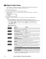
Page 140: ...key to return to the previous programming level Report Codes Zones Quick Keys Parameter Default 6 6 2 2 1 1 Alarm 00 To report an alarm in a designated zone 6 6 2 2 2 2 Alarm Restore 00 To report an alarm restoral in the designated zone 6 6 2 2 3 3 Trouble Supervision 00 To report a Day Zone violation during the disarmed period and or a wireless zone trouble caused by a management failure 6 6 2 2 ...

Page 141: ...ollowing display appears 3 Access and configure the parameters in the Accessory Tamper menu shown in the table below as follows O Use the 1 to 7 keys to select the event category keypad Utility Output module and so on O Press the event number keypad tamper utility output tamper restore and so on O Enter the 2 digit keypad utility output and the corresponding 2 digit Report Code representing the ev...

Page 142: ...ore to Normal Code for Code for Wireless Zone expansion modules 6 6 3 3 7 7 Advanced Voice Expansion Module 00 1 Advanced Voice Module Tamper Tamper Code for Advanced Voice module 2 Advanced Voice Module Tamper Restore Tamper Restore to Normal Code for Code for Advanced Voice module 6 6 3 3 8 8 Siren 00 1 Siren Tamper Tamper Code for tamper alarm from BUS siren 2 Siren Tamper Restore Tamper Restor...

Page 143: ... sounder wired to the Main Panel 3 Phone reports a trouble condition regarding telephone service management 4 AC Loss reports a trouble condition regarding the AC power supply to the ProSYS 5 AUX Fail reports a trouble condition regarding the loss of Auxiliary Power either continuous or switched supplied by the ProSYS 6 Clock Not Set reports a trouble condition caused by a Clock Not Set 7 BUS Fail...

Page 144: ...ring to normal of the telephone service to ProSYS 4 AC reports the restoring to normal of AC power supply to the ProSYS 5 AUX reports the restoring to normal of Auxiliary Power either continuous or switched supplied by the ProSYS 6 Clock Is Set 2 digit code to report that the system s clock is now set 7 BUS Comm report the restoring to normal of the system s 4 wire BUS 8 False Code reports user vi...

Page 145: ...e 2 digit code representing the event O Press O Press the key to return to the previous programming level Report Codes Power Supply Accessory Module Trouble Quick Keys Parameter Default 6 6 5 5 1 1 Trouble Conditions 00 Trouble Codes assigned to the ProSYS Main Panel 1 Low Battery reports the detection of a weak or missing standby battery 2 Bell reports a trouble condition regarding the management...

Page 146: ... From the Report Codes menu press 6 to access the Arm Codes menu options The following display appears 3 Access and configure the parameters in the Arm Codes menu shown in the table below as follows O Press the number of the event to be programmed O Enter the 2 digit code representing the event Refer to Appendix C Report Codes for any special instructions O Press O Press the key to return to the p...

Page 147: ...Code transmitted when the system is armed with this specific device 6 6 7 7 Report Codes Disarm Codes Openings The Disarm Codes menu contains codes that enable the reporting of the Opening Signals generated when the system is DISARMED opened in various conditions To access the Disarm Codes menu 1 Access the Report Codes menu as described on page 137 2 From the Report Codes menu press 7 to access t...

Page 148: ...odes Miscellaneous The Miscellaneous menu contains codes that enable the reporting of miscellaneous events to the MS To access the Miscellaneous menu 1 Access the Report Codes menu as described on page 137 2 From the Report Codes menu press 8 to access the Miscellaneous menu options The following display appears 3 Access and configure the parameters in the Miscellaneous menu shown in the table bel...

Page 149: ... the MS Refer to Abort Alarm page 52 for additional details 6 6 8 8 8 8 Self Test OK 00 Report Code for confirmation of a successful Zone Self Test Refer to page 80 for additional details 6 6 8 8 9 9 Self Test Failure 00 Report Code for verification of an unsuccessful Zone Self Test Refer to page 80 for additional details 6 6 8 8 0 0 More More Options 6 6 8 8 0 0 1 1 Cancel Report 00 Report Code f...

Page 150: ... and Contact ID 6 6 9 9 Report Codes Special Communication The Special Communication menu enables you to program the 3 digit Report Codes for MS Communication Formats requiring 3 digit Event Codes Refer to the ProSYS Installer Programming Worksheets for additional details To access the Special Communication menu 1 Access the Report Codes menu as described on page 137 2 From the Report Codes menu p...

Page 151: ...0 Enter the Wireless Button Module s 1 digit ID 1 Enter the 2 digit Report Code for the module s detection of jamming interference according to the parameters established on page 48 2 If this event is not to be transmitted use the 00 default 3 Press the key to return to the previous programming level 6 6 0 0 2 2 2 2 Jamming Trouble Restore 00 Enter the Wireless Button module s 1 digit ID 1 Enter t...

Page 152: ...capacity 6 6 0 0 4 4 Wireless Button 00 Press 4 to access each sub category as shown below 6 6 0 0 4 4 1 1 Wireless Button Low Battery 00 Report Code for low battery condition 6 6 0 0 4 4 2 2 Wireless Button Low Battery Restore 00 Report Code for correction of low battery condition 6 6 0 0 5 5 Siren Trouble 00 Press 5 to access each sub category as shown below 6 6 0 0 5 5 1 1 Trouble 00 Report cod...

Page 153: ...word GPRS IP fault GPRS Connection PUK code fault 6 Pre alarm report Code for correction of low battery condition 6 6 0 0 6 6 2 2 Trouble Restore 00 Report codes for GSM faults restore 1 Tamper Restore report code for the restore of the GSM box tamper alarm condition 2 Communication Trouble Restore report code for the restore of communication trouble between the GSM module and the ProSYS 3 Mains T...

Page 154: ... menu Refer to the ProSYS User s Manual To access the Accessories menu From the main Installer Programming menu press 7 or press the or keys until you find the number 7 Accessories option and then press The first submenu ADD DEL MDL appears You are now in the Accessories menu and can access the required submenus as described in the following sections 7 7 1 1 Accessories Add Delete Module Default N...

Page 155: ...alling External Modules and Devices 3 Place the cursor on the TYPE field and use the key to toggle between the five options provided to select the keyboard type as follows NONE LCD keypad KP08 8 LED keypad KP16 16 LED keypad LCDP proximity LCD keypad WLKP wireless keypad 4 Press to store your choice and proceed to STEP 2 ASSIGNING A PARTITION below If a keypad is found and NONE has been selected t...

Page 156: ...ormation about the selected partitions can also be viewed on the specific keypad 1 After pressing to store your partition choice The following display appears 2 For each partition 1 to 8 use the key to toggle between Y YES and N NO NOTE The xx represents the ID number of the keypad 3 Press to repeat the process for other keypads in the system up to 16 4 Press to return to the previous programming ...

Page 157: ... process for other Zone Expanders in the system up to 8 depending on your installed model 6 Press to return to the previous programming level If a Zone Expander is found and NONE has been selected the following display appears 7 To return to the previous display press OR Press the key to select Y YES and press to confirm the delete 7 7 1 1 3 3 Utility Output Module U008 1 Press 3 The following dis...

Page 158: ...es in the system up to the system s maximum of 8 depending on your installed model 6 Press to return to the previous programming level If a Utility Output module is found and NONE has been selected the following display appears 7 Press to return to the prior display OR Press to select Y YES and press to confirm the delete 7 7 1 1 4 4 Power Supply Module NONE 1 Press 4 The following display appears...

Page 159: ...ess to select Y YES otherwise press The Partition display appears NOTE If YES is selected the system will look for detect and sound any problems in the sounder circuit P 12345678 PS 1 Y 7 Use the or keys to select a partition number and then use the key to toggle Y YES or N NO to assign that partition to the power supply 8 Repeat the process for any other Power Supply modules in the system up to t...

Page 160: ...al 999 Event Log Module 3 Press to confirm and store your choice If an Event Logger is found and NONE has been selected the following display appears 4 Press to return to the prior display OR Press to select Y YES and press to confirm the delete 7 7 1 1 6 6 Wireless Button Module NONE The Wireless Button module is a wireless receiver add on designed to process signals from up to eight handheld wir...

Page 161: ...firm the delete 7 7 1 1 7 7 Printer Module NONE NONE PRNE PRNA PRN2 1 Press 7 The following display appears 2 Use the or keys to position the cursor over ID 1 and type in the Printer module s ID number that you are assigning or deleting The first or only Printer module must be assigned the first ID number which is 1 the system can support two such modules 3 Place the cursor over the TYPE field and...

Page 162: ... pressing the 1 key 7 7 1 1 8 8 Access Control 1 Press 8 The following display appears 2 Use the or keys to position the cursor in the ID 1 field and type in the Access Control module s ID number as defined by the dip switches that you set when you installed the module 3 If required position the cursor in the TYPE field and use the key to toggle and choose the AC option 4 Press to add the Access C...

Page 163: ...ance reader In order to use the module s antipassback feature you must install both readers on one door one reader for the entrance and one reader for the exit You can then enable disable the antipassback feature as required The default setting for the antipassback feature is set to NO 7 Repeat steps 2 to 6 to add additional Access Control modules if required OR Press to return to the previous pro...

Page 164: ...rtitions that will be affected by the instant arm function 9 Press The following display appears 10 Use the key to toggle and choose the required option If YES the ready status will be indicated on the reader If NO no ready status indication will be indicated on the reader 11 Press The following display appears KEY READER ID 01 SHOW ARM Y KEY READER ID 01 SHOW ARM Y If YES the Arm status will be i...

Page 165: ...phone Refer to the ProSYS User s Manual for additional details 7 7 1 1 9 9 3 3 Advanced Communication Module ACM 1 Press 3 The following display appears ACM MODULE TYPE NONE ACM MODULE TYPE NONE 2 With the cursor positioned at the TYPE field use the key to toggle and choose the ACM option 3 Press to store your choice NOTE If ACM module is found and NONE has been selected Press to return to the pri...

Page 166: ...ay appears SIREN 1 SQUAWK STROBE Y 11 Use the key to toggle Y YES or N NO If yes the siren will flash to indicate the armed status 12 Repeat steps 2 to 11 for other sirens if needed 7 7 1 1 9 9 5 5 BUS Zones This BUS Zone expander enables the ProSYS to support 32 addressable detectors see below types on the main unit without the need to add any additional hardware zone expanders virtual zones The ...

Page 167: ... detector ILUN3 Industrial Lunar Grade 3 detector iDTG3 iWISE DT Grade 3 detector iQDG3 iWISE QUAD Grade 3 detector 4 Press to confirm Repeat the process for the other BUS detectors NOTE If BUS detector is found and NONE has been selected Press to return to the prior display OR Press the key to select Y YES and press to confirm the delete 7 7 1 1 9 9 6 6 GSM GPRS Module 1 Press 6 The following dis...

Page 168: ...th the modules you defined in the Add Delete Module menu page 154 or in the Auto Settings menu page 170 To access the Verify Module menu 1 Access the Accessories menu as described on page 154 2 From the Accessories menu press 2 to access the Verify Module menu options The following display appears 3 Use the or keys to scroll down the list of displayed accessory devices shown in the examples below ...

Page 169: ...100 means that there are BUS connection problems for example bad wiring or cabling located in a harsh electrical environment or two modules in the same family have been given the same ID number 7 7 4 4 Accessories BUS Scanning The BUS Scanning menu scans the BUS and reports all modules found To access the BUS Scanning menu 1 Access the Accessories menu as described on page 154 2 From the Accessori...

Page 170: ...ettings The Auto Settings menu enables you to perform automatic setting of the accessories connected to the system by using the BUS scanning feature This process also runs automatically when the system is defaulted and the AC power is turned on refer to the Accessing the Installer Programming Menu section of Chapter 4 Programming the ProSYS for additional details To access the Auto Settings menu 1...

Page 171: ... transmitters with the following options Away Stay Disarm Panic and Utility Output activation After you access the Key fobs menu from the main Installer Programming menu as described in this section you can access the following submenu 8 8 1 1 1 1 Wireless Button Parameters below 8 8 1 1 2 2 Wireless Button Allocation page 173 To access the Key fobs menu Access the Miscellaneous menu as described ...

Page 172: ... or STAY arming can be defined as instant or delayed Exit Delay 3 After selecting the Arming type and mode of operation press The system moves to the next key and the following display appears 4 Set the parameters for the Disarm Key 2 used to perform the Disarming operation from the following options O NONE The key is disabled default O DISARM The key ID is used for disarming its assigned partitio...

Page 173: ... other wireless buttons 8 8 1 1 2 2 Wireless Button Allocation Default NONE This procedure is required when using a 4 key wireless transmitter To access the Wireless Button Allocation menu 1 Access the Miscellaneous menu as described on page 170 2 From the Miscellaneous menu press 2 to access the Wireless Button Allocation menu options The following display appears 3 Use the or keys to position th...

Page 174: ... Defines the number of times that the strobe will blink in a minute 1 20 Times Min 2 30 Times Min 3 40 Times Min 4 50 Times Min 5 60 Times Min 8 8 2 2 3 3 Strobe Arm SQK Default 01 Range 01 20 seconds The time that the strobe will blink when the system is armed Note If the siren s squawk strobe is defined as NO Refer to the Add Delete Module Siren section page 165 this parameter will be ignored 8 ...

Page 175: ...3 3 2 2 GSM Control page 181 8 8 3 3 1 1 GSM Parameters This sub menu enables you to program parameters that ensure proper operation of the GSM module GSM Parameters Quick Keys Parameter Default 8 8 3 3 1 1 1 1 GSM Mode Configures the GSM module modes of operation voice channel 1 GSM Back Up the outgoing calls are executed through the PSTN line When the PSTN line is not available for the time defi...

Page 176: ...ording to the time given by the provider 8 8 3 3 1 1 3 3 Prefix Prefix Number Definition The following parameters Quick Key 8 2 1 3 1 to 8 2 1 3 0 are used for the prefix conversion performed when dialing with the GSM module through the voice channel only A description of the methodology is detailed below For better understanding the procedure use the examples on page 177 Note The Prefix Numbers C...

Page 177: ...ling from the GSM network Example The module is connected to PBX Private Branch Exchange which has a PSTN line in area code 03 after dialing the access number 9 The outgoing calls through the GSM module are allowed to the following telephone numbers 03 910 5555 owner s residence 052 366 4444 owner s cellular 054 366 5555 owner s spouse cellular The telephone numbers definition in the panel should ...

Page 178: ...k an APN Access Point Name code is required The APN code differs from country to country and from one provider to another the APN code is provided by your cellular provider The ProSYS supports an APN code field of up to 30 alphanumeric characters and symbols etc 8 8 3 3 1 1 5 5 2 2 GPRS User Name Enter user name for the GPRS network if required The User name is provided by your provider The ProSYS...

Page 179: ...ll 1st Primary N A N A Call 2nd N A Primary N A Call 3rd N A N A Primary Call All Primary Primary Primary 1st Backup 2nd Primary If MS 1 is OK Secondary else MS 1 Fails Backup N A 1st Backup 2nd 3rd Primary If MS 1 is OK Secondary else MS 1 Fails Backup If MS 2 is OK Secondary else MS 2 Fails Backup 1st Backup 3rd Call 2 Primary Primary If MS 1 is OK Secondary else MS 1 Fails Backup 2nd Backup 3rd...

Page 180: ...GPRS Backup 00009 x10 sec 0 65535 sec Defines the polling interval through the backup channel When using the default time a polling message is sent every 90 seconds When the GPRS Backup polling time is defined as 0 no polling message is sent to the MS when the MS channel is in the Backup polling mode 8 8 3 3 1 1 6 6 Email The following programming parameters 8 2 1 6 1 to 8 2 1 6 6 are used to enab...

Page 181: ...SMS was sent from and compares them to the last digits of the Follow Me telephone numbers defined in the ProSYS If the digits coincide the number is recognized as one of the Follow Me numbers and the operation will be executed Set the number of digits to be checked by the module 8 8 3 3 1 1 8 8 RSSI Level The GSM Signal Level RSSI depends on the location in which the GSM GPRS BUS Module is install...

Page 182: ...ys until you find the number 9 Access Control option and then press The first submenu DOOR DEFINE appears You are now in the Access Control menu and can access the required submenus as described in the following sections 9 9 1 1 Access Control Door Define The Door Define menu contains parameters that enable you to define the door parameters for the Access Control module To access the Door Define m...

Page 183: ...pen delay door force delay and the door alarm delay settings 1 Press 2 and press 2 Select the required door time settings option O Open Delay O Door Force Delay O Door Alarm Delay 9 9 1 1 2 2 1 1 Open Delay 4 seconds 1 99 seconds 1 Determines the amount of time that the door relay is open after a valid entry 2 Press 2 and to enter the door time settings 3 Press 1 and 4 Enter the number of seconds ...

Page 184: ...the ProSYS the system sends a fire alarm notification to the Access Control module which sets the door relay to the required position during the fire alarm 1 Press 3 and 2 Toggle the key to select the appropriate option as follows O YES Keeps the door open during a fire alarm O NO Keeps the door closed during a fire alarm 3 Press 9 9 1 1 4 4 Door Input Settings Defines the status of the door relay...

Page 185: ...r Barcode technologies The position that you define is applicable to all cards in the system By default the system reads the first 8 digits of the card track If the first 8 digits of the card are identical this may occur on credit cards where the first digits may be for example the bank code or the name of the credit card company it will be necessary to read 8 digits from a different section of th...

Page 186: ...e following technology combinations Keypad and proximity Keypad and magnetic To access the Special Code menu 1 Access the Access Control menu as described on page 182 2 From the Access Control menu press 3 to access the Special Code menu options The following display appears 3 Access and configure the parameters in the Special Code menu as follows Access Control Special Code Quick Keys Parameter D...

Page 187: ...O Save your changes by pressing The following display appears When the data has been saved the following display appears 3 Next the system will perform a Tamper Test The following display appears TESTING TESTING PLEASE WAIT PLEASE WAIT TESTING TESTING PLEASE WAIT PLEASE WAIT If a tamper occurs in the system Bell box or other the display will show a list of the tamper faults in the system It is adv...

Page 188: ...S Installation and Programming Manual O Discard your changes by using the key to change the Y YES to N NO on the display and then press The following display appears The keypad returns to the normal user display ...

Page 189: ... enter a code for each parameter that requires programming When entering a parameter that is not authorized for installer programming the keypad will produce three short beeps and the LCD will display the parameter again The column headings for the relevant procedures appear as follows Column Heading Description Quick Keys A shortcut to program an option The shortcuts are listed in numerical seque...

Page 190: ...TIVITIES 1 UTIL OUTPUT You are now in the Activities menu and can access the following parameters as described below Activities Quick Keys Parameter Range 2 2 0 0 2 2 Overload Restore The Grand Master Installer Sub installer Manager can use this option to restore the auxiliary power from a power supply if overload condition is still present disconnect all loads from AUX Output 2 2 0 0 3 3 Check Cr...

Page 191: ... menu as described in this section you can access the following parameters 3 3 1 1 Trouble page 191 3 3 3 3 Not Ready Status page 192 3 3 4 4 Zone Status page 192 3 3 5 5 Event Log page 192 3 3 6 6 Service Info page 192 To access the View menu From the main User Programming menu press 3 or press the or keys until you find the number 3 View option and then press The first submenu Trouble appears VI...

Page 192: ... or the key to move backward 10 events 3 3 6 6 Service Info 1 Installer displays any previously entered service information 2 System version displays the system software version 4 4 Maintenance After you access the Maintenance menu from the main User Programming menu as described in this section you can access the following parameters 4 4 1 1 Keypad Test page 193 4 4 2 2 Battery Test page 193 4 4 ...

Page 193: ...0 0 1 1 Walk Test The walk test enables the installer or the Grand Master to easily test and evaluate the operation of each zone in the system NOTE The difference between performing a walk test with an installer code compared to using the Grand Master code relates to a tamper condition A tamper during a Grand Master Walk Test will cause an alarm in the system while a tamper during an Installer Wal...

Page 194: ...hone The provider s phone number to which the credit level SMS message will be sent to when performing manual credit level check or a service command Note When using a service command this field is ignored 3 The provider s telephone number from which an automatic SMS credit status message will be sent from This telephone number has to be defined otherwise the incoming SMS credit status message wil...

Page 195: ...for example the address and or telephone number of the premises This message is up to 10 seconds long Partition Message User defined name for the partition in which the event occurred for example First floor The Partition message can be up to 2 seconds long and is only announced when the Event announcement message concerns a partition Zone Message User defined name for the zone in which the event ...

Page 196: ...to play the common message Press 2 to record a new message The following display appears PRESS TO START MESSAGE RECORD Press and speak your message into the microphone The counter in the display counts down the seconds remaining until the recording will stop PRESS TO STOP REC TIME 10 Recording stops automatically after 10 seconds If you finish your message in 9 seconds or less press the key to sto...

Page 197: ...sh your message in less than 2 seconds press to stop recording The default partition messages for partition 1 to Partition 8 are Partition 1 to Partition 8 respectively 9 9 4 4 2 2 3 3 Zone Message 1 Press 2 The following display appears ZONE 01 01 32 ZONE 001 2 Select the zone number and press 3 Press the required option as follows Press 1 to play the zone message Press 2 to record a new message ...

Page 198: ...er to which you want to assign an appliance and press The following display appears CHOOSE UO 01 OUTPUT 01 3 The options in the Choose UO menu represent the Follow Code utility outputs Select the number representing the appropriate output for the message selected above or select 00 for no ouput to be assigned to a message Press 4 Press the required option as follows Press 1 to play the utility out...

Page 199: ...perform a local test message Access the Miscellaneous menu as described on page 194 1 From the Miscellaneous menu press 3 to access Test Message and press The following display appears TEST MESSAGE 1 SEND MESSAGE 2 Press 2 The message Test Message is repeated continuously for 90 seconds and the following display appears PRESS ANY KEY TO STOP VM TEST 3 Press any key to stop the test message ...

Page 200: ...33 cm x 9 8 cm Main Board Dimensions 20 cm x 11 5 cm x 6 5 cm Fuses F3 Responsible for Battery Power 3 0 A AUX Automatic fuse BELL Automatic fuse Keypads 8 LED 16 LED KCL KCLP Current Consumption 8 LED 75 mA maximum 16 LED 75 mA maximum KCL 100 mA maximum Proximity KCL 160 mA maximum Main Panel Connection 4 wire BUS up to 300 m from Main Panel Dimensions 16 2 cm x 12 2 cm x 3 cm Touchscreen Keypad...

Page 201: ...ntact rating 5 A 24V DC Main Panel Connection 4 wire BUS up to 300 m from Main Panel Dimensions 10 5 cm x 6 6 cm x 2 2 cm Utility Output Expansion Module 8 Output Current Consumption 25 mA typical 30 mA maximum Contacts Open Collector Active Pull Down 70 mA maximum Main Panel Connection 4 wire BUS up to 300 m from Main Panel Dimensions 10 5 cm x 6 6 cm x 1 8 cm 1 5 Power Supply Expansion Module In...

Page 202: ...maximum Main Panel Connection 4 wire BUS up to 300 m from Main Panel Dimensions 10 5 cm x 6 6 cm x 1 8 cm Printer Module Current Consumption 10 mA maximum Main Panel Connection 4 wire BUS up to 300 m from Main Panel Dimensions 6 2 cm x 5 3 cm x 1 6 cm X 10 Transmitter Module Current Consumption 30 mA maximum Main Panel Connection 4 wire BUS up to 300 m from Main Panel Dimensions 10 5 cm x 6 6 cm x...

Page 203: ...e BUS up to 1000 ft 300 m Dimensions 40 x 43 6 x 22 mm GSM GPRS Communication Module Input Power 13 8VDC 10 Current Consumption During Communication 300mA During Standby 70mA Battery Not supplied Lead Acid rechargeable 12VDC 1 2Ah Main Panel Connection 4 wire BUS up to 300 m Dimensions in metal casing Width x Height x Depth 185 x 275 x 65 mm With antenna installed 185 x 275 x 65 mm Main Board Dime...

Page 204: ... with FAST and extended loop response definitions ProSYS EZ8G3 8 Zone Expansion Module TEOL termination ProSYS EZ16G3 16 Zone Expansion Module TEOL termination ProSYS BZE Bus Zone Expander Wireless Zone Expanders Description ProSYS EW08 8 Wireless Zone Expansion 868 MHz or 433 MHz ProSYS EW16 16 Wireless Zone Expansion 868 MHz or 433 MHz ProSYS EWR Wireless Repeater 868 MHz or 433 MHz Wireless Tra...

Page 205: ...er Supply inside midium Metal box Tamper RP128EPSPUKA ProSYS 3APSB 3A Switched Power Supply inside large metal box Tamper transformer RP128PSPSEUA ProSYS 3APSB 3A Switched Power Supply inside large metal box Tamper No transformer RP128PSPSUSA Programmable Output Devices Description ProSYS E04 4 relay utility output expansion module ProSYS E08 4 transistor utility output expansion module Printer Mo...

Page 206: ...PSTN Modem 2400 BPS Description ProSYS MD2400 Fast PSTN external modem 2400 BPS IP GSM Receiver Description IP Receiver GSM IP Receiver Software External Sounder Description ProSound 200P Prosound external sounder double skin with anti foam protection ProSound 200 Prosound external sounder double skin Upload Downlaod Description ProSYS EE Program Transfer Module ProSYS EBA RS 232 485 Local U D Ada...

Page 207: ...ISE 825DTBG2 iWISE DT AM Grade 2 25m 82 ft iWISE 800QBG2 iWISE Quad 15m 50 ft AM Grade 2 Demonstration Board Description ProSYS DBL ProSYS Laptop demo board Boxes Description ProSYS B2 ProSYS Metal box tamper AGM B4 GSM Metal box tamper for accessories ProSYS B5 ProSYS plastic accessories tamper ...

Page 208: ...3 9C9 Closing Not Identified CL 34 CDA 24 Hour Report 24H 35 BAB AC Fail AC 36 EAB AC Restoral EAC 37 AEA Low Battery LO 38 EEA Low Bat Rest ELO 39 DFF Bell Trouble dBL 4A EFF Bell Trouble Rest EBL 41 DEE Phone Trouble dPL 42 EEE Phone Trouble Rest EPL 43 DDD Duress dU 44 EBA Opening Out of Window EOP 45 ECA Closing Out of Window ECL 46 CAC Test CH 47 Axx Alarm Axx 48 Dxx Trouble dxx 49 Exx Restor...

Page 209: ...m 38 130 Burglary 39 131 Perimeter 4A 132 Interior 41 133 24 Hour 42 134 Entry Exit 43 135 Day Night 44 136 Outdoor 45 137 Tamper 46 140 General Alarm 47 144 Sensor Tamper 48 145 Accessory Tamper 49 150 24 Hour Non Burg 5A 155 Foil Break 51 156 Day Trouble 52 300 Main Aux Trouble 53 301 Main AC Trouble 54 302 Main Battery Trouble 55 305 System Reset 56 321 Main Bell Trouble 57 330 Power Supply Tro...

Page 210: ...Request 7A 421 False Security Code 71 570 Zone Bypass 72 574 Forced Arm 73 602 Communication Test 74 143 Exp Module Fail 75 307 Self test Fail 76 334 Repeater Fail 77 336 Local Printer Fail 78 355 Loss of Radio Supervision 79 381 Loss of Supervision RF 8A 384 Rx Transmitter Low Bat 81 406 Cancel 84 606 Listen In to Follow 85 139 Confirmed alarm 86 312 Power supply overload 87 999 MS Polling 626 Cl...

Page 211: ...lose Area System has been partly armed 2A CJ Late Close 2B CK Early Close 2C CL Closing Report 2D CP Automatic Closing User Number 2E CS Closing Keyswitch 2F CZ Point Closing 30 FT Dummy 31 DD Access Denied Unknown Code 32 DT Access Trouble 33 ER Expansion Device Restoral 34 ET Expansion Device Trouble 35 FA Fire Alarm 36 FB Fire Bypass 37 FC Fire Cancel 38 FH Fire Alarm Restoral 39 FJ Fire Troubl...

Page 212: ...re 4C MT Medical Trouble 4D OA Automatic Opening 4E OC Cancel Report 4F OG Open Area Area Number 50 PT Dummy 51 OJ Late Open 52 OK Early Open 53 OP Opening Report 54 OR Disarm from Alarm 55 OS Opening Keyswitch 56 OZ Point Opening Zone or Point 57 PA Panic Alarm 58 PH Panic Alarm Restore 59 PJ Panic Trouble Restore 5A PT Panic Trouble 5B QA Emergency Alarm 5C QH Emergency Alarm Restore 5D QJ Emerg...

Page 213: ...estoral 72 XQ RF Interface 73 XR Transmitter Battery Restoral 74 XS RF Receiver Tamper 75 XT Transmitter Battery Trouble 76 YA Bell Trouble 77 YC Receiver Transmitter Communication Fail 78 YH Bell Restoral 79 YK Communication Restoral 7A YM System Transmitter Receiver Battery Missing 7B YP Power Supply Trouble Transmitter Receiver 7C YQ Power Supply Restored Transmitter Receiver 7D YR System Batte...

Page 214: ...14 ProSYS Installation and Programming Manual New Codes If a new code not supported by the Main Panel is required it can be added to the list using the SPECIAL programming item up to 30 additional codes ...

Page 215: ...CM succeeded to make an event log ACM HARDWAR E ERR Internal hardware error in the ACM ACM HARDWAR E OK No hardware error in the ACM ACM MAIL ERROR ACM failed to send an Email ACM MAIL OK ACM successfully send an Email ACM MS X ERROR Communication failure to MS X The ACM failed to report to MS X ACM MS X OK Communication to MS X is OK ACM NETWORK ERR ACM failed to connect to network Ethernet ACM N...

Page 216: ...Y ARM D P X C YY Group D on Partition X is armed by user YY ARM D P X WB YY Group D on partition X is set by wireless keyfob YY ARM FAIL P X Fail to Arm Partition X by Guard due to not ready zones ARM P X C YY Partition X armed by user YY ARM P X WB YY Partition X armed by wirelesskeyfob YY AUT TST FAIL Failure of zone self test AUTO TEST OK Automatic zone self test OK AUX RS PS X Restore of Aux p...

Page 217: ... Time defined by user No XX COM OK AC X Bus communication OK with Access Control module X COM OK ACM Bus communication OK with the ACM module COM OK KP XX Bus communication restore with keypad ID XX COM OK KR XX Bus communication OK with Proximity Key Reader XX COM OK PRN X Bus communication OK with the printer module X COM OK VOICE Bus communication OK with Advanced Voice module COM OK WBA X Bus ...

Page 218: ...ST RST Z XXX Dust trouble restore from WatchOUT DT BUS zone XXX DUST Z XXX Dust trouble from WatchOUT DT BUS zone XXX EE AC UPLOAD Load new parameters from PTM accessory ELOG COMM OK Bus communication restore with event logger expander ID X ELOG NO COMM Bus communication failure with event logger expander ID X ENTER PROGRM Entering Installer programming from keypad or UD software EXIT PROGRAM Exit...

Page 219: ...M MDL COMM OK Internal GSM GPRS BUS Module trouble restore GSM MODULE COMM Internal GSM GPRS BUS Module trouble GSM MS OK GPRS communication to the MS is OK GSM MS TROUBLE GPRS communication failure to the MS GSM NET AVAIL GSM Network is not available GSM NET AVAIL OK GSM Network is available GSM NET QUAL OK The GSM RSSI level is OK according to the defined level GSM NET QUALITY The GSM RSSI level...

Page 220: ...tch zone XXX KSW B Z XXX P Y Group B in partition Y is armed by keyswitch zone XXX KSW C Z XXX P Y Group C in partition Y is armed by keyswitch zone XXX KSW D Z XXX P Y Group D in partition Y is armed by keyswitch zone XXX KSW DIS Z XXX P Y Partition Y is disarmed by keyswitch zone XXX L BAT RSTR WB XX Low battery trouble restored from wireless keyfob XX LB RSTR Z XXX Low battery restore from wire...

Page 221: ...wer supply ID X NO COM AC X Bus communication failure with Access Control module X NO COM ACM Bus communication failure with the ACM module NO COM KP XX Bus communication failure with keypad ID XX NO COM KR XX Bus communication failure with Proximity Key Reader XX NO COM PRN X Bus communication failure with the printer module X NO COM VOICE Bus communication failure with Advanced Voice module NO C...

Page 222: ...X FUL RS Printer module X buffer is down to less than 75 of its capacity PRN X FULL Printer module X buffer is full to more than 75 of its capacity PROX FAIL S X Fail in the proximity anti approach protection in siren X PROX OK SIREN X Proximity anti approach protection is restored in siren X PROX TMP RS S X Proximity tamper restore from siren ID X PROX TMP SIREN X Proximity tamper from approachin...

Page 223: ...ander ID X TAMPER ZE X Tamper alarm in zone expander ID X TAMPER ZN XXX Tamper alarm from zone XXX TMP RS EVLOG Tamper alarm restore from event log expander ID X TMP RS KP XX Keypad tamper restore TMP RS PS X Tamper alarm restore from power supply expander ID X TMP RS UO X Tamper alarm restore from UO expander ID X TMP RS VOICE Tamper alarm restore from Advanced Voice module TMP RS WBA X Tamper al...

Page 224: ... communication OK with the external modem X Modem TAMP ER Tamper alarm in external modem X Modem TAMP R OK Tamper alarm restore in external modem XModem Comm Fall BUS communication failure with the external modem XModem No Phone No phone connection to the external modem XModem Phone OK Phone connection restored to the external modem Z XXX AUT BAD Zone self test failed zone XXX Z XXX AUTO OK Zone s...

Page 225: ... False Code Trouble 1219 Abort Alarm 1233 Area 1206 Bell Sqk 1220 Summ Win Clock 1234 DIS Keypad Auto Disarm Exists 1207 Bell 30 10 1221 Forced KSW 1235 Aud Prx TMP 1208 Alm Phone Cut 1222 Pager 1236 AM Tamper 1209 3 Min Bypass 1223 Arm Prewrn 1237 Prox AM Tamper 1210 Dbl Ver Fire Al 1224 L Batt Arm 1238 SIRN AUX TMP 1211 Aud Panic 1225 ENG Tamper 1239 GSM Pre Alarm 1212 Buzz Bell 1226 Blank Displ...

Page 226: ... 23zz14 Fire 23zz22 Latched KSW Dly 23zz07 I Ex En2 23zz15 Panic 24 Zone Sound 241 Silent 243 Buzzer Only 245 Door Chime 242 Bell Only 244 Bell Buzzer 246 Bell A Buz D 25 Termination 2501 N C 2505 BUS Zone 2509 BZ Input DEOL 2502 EOL 2506 TEOL 2510 BZ Input N O 2503 DEOL 2507 BZ Input N C 2511 BZ Input TEOL 2504 N O 2508 BZ Input EOL 26 Loop Response 27 Cross Zone 271 Zone Crossing 28 Labels 29 Ma...

Page 227: ...sarm Follow 3202 Alarm Follow 3210 Chime Follow 3218 Bell Follow 3203 Arm Follow 3211 Ex En Follow 3219 Bell Stay Off 3204 Burglary Follow 3212 Fire Trouble Follow 3220 Zone Bypass 3205 Fire Follow 3213 Day Zone Follow 3221 Auto Arm Alarm 3206 Panic Follow 3214 Gen Trouble Follow 3222 Zone Loss Alarm 3207 Special Emergency Follow 3215 Stay Follow 3208 Duress Follow 3216 Tamper Follow 33 Zone 331 Z...

Page 228: ...512 Show Kissoff 56 Parameters 561 MS Retries 564 Dial Tone Time 567 Pulse Duty Cycle 562 FM Retries 565 Redial Wait 568 Swinger Limit 563 Rings to U D 566 Dial Method 569 VM Retries 57 Report Split 571 MS Arm Disarm 573 MS Non Urgent 575 Email See Email table on page E 6 572 MS Urgent 574 Follow Me 576 Event Log 58 Alarm Restore 581 On Bell Time Out 582 Follow Zone 583 At Disarm 59 Periodic Test ...

Page 229: ...Siren LED 827 Bat Load Test 83 GSM See GSM table 9 Access Control 91 Door Define 91dd1 Partitions 91dd3 Door Fire 91dd5 Door Label 91dd2 Door Time 91dd4 Door Input 92 Card Code Pos 93 Special Code ACM 502 ACM Parameters 5021 ACM IP Address 5027 Gateway IP 50203 DNS 1 IP 5022 ACM UD Port 5028 Software Update IP 50204 DNS 2 IP 5023 ACM AUX1 Port 5029 Software Update Port 50205 NTP IP 5024 ACM AUX2 P...

Page 230: ...N Lost 83122 GSM Lost 83123 SIM Expire Date 8313 Prefix 8313 1 to 2 PBX Prefix 8313 3 to 8 Prefix Constant 83139 Remove Prefix 83130 Add Prefix 8314 PIN Code 8315 GPRS 83151 APN Code 83152 GPRS User Name 83153 GPRS Password 83154 GPRS MS Polling 831541 GPRS Primary 831542 GPRS Secondary 831543 GPRS Backup 8316 Email 83161 SMTP IP Address 83162 SMTP Port 83163 SMTP User Name 83164 SMTP Password 831...

Page 231: ... that its product may not be compromised or circumvented that the product will prevent any personal injury or property loss by burglary robbery fire or otherwise or that the product will in all cases provide adequate warning or protection Seller in no event shall be liable for any direct or indirect damages or any other losses occurred due to any type of tampering whether intentional or unintentio...

Page 232: ...om Spain Tel 34 91 490 2133 E mail support es riscogroup com China Shenzhen Tel 86 755 82789285 E mail support cn riscogroup com France Tel 33 164 73 28 50 E mail support fr riscogroup com Poland Tel 48 22 500 28 40 E mail support pl riscogroup com Belgium Benelux Tel 32 2522 7622 E mail support be riscogroup com Israel Tel 972 3 963 7777 E mail support riscogroup com USA Tel 1 631 719 4400 E mail...

Reviews: