Rinnai ENERGYSAVER RHFE-308FTR Installation Manual Download Page 20

Rinnai 

20

 ES_FIM

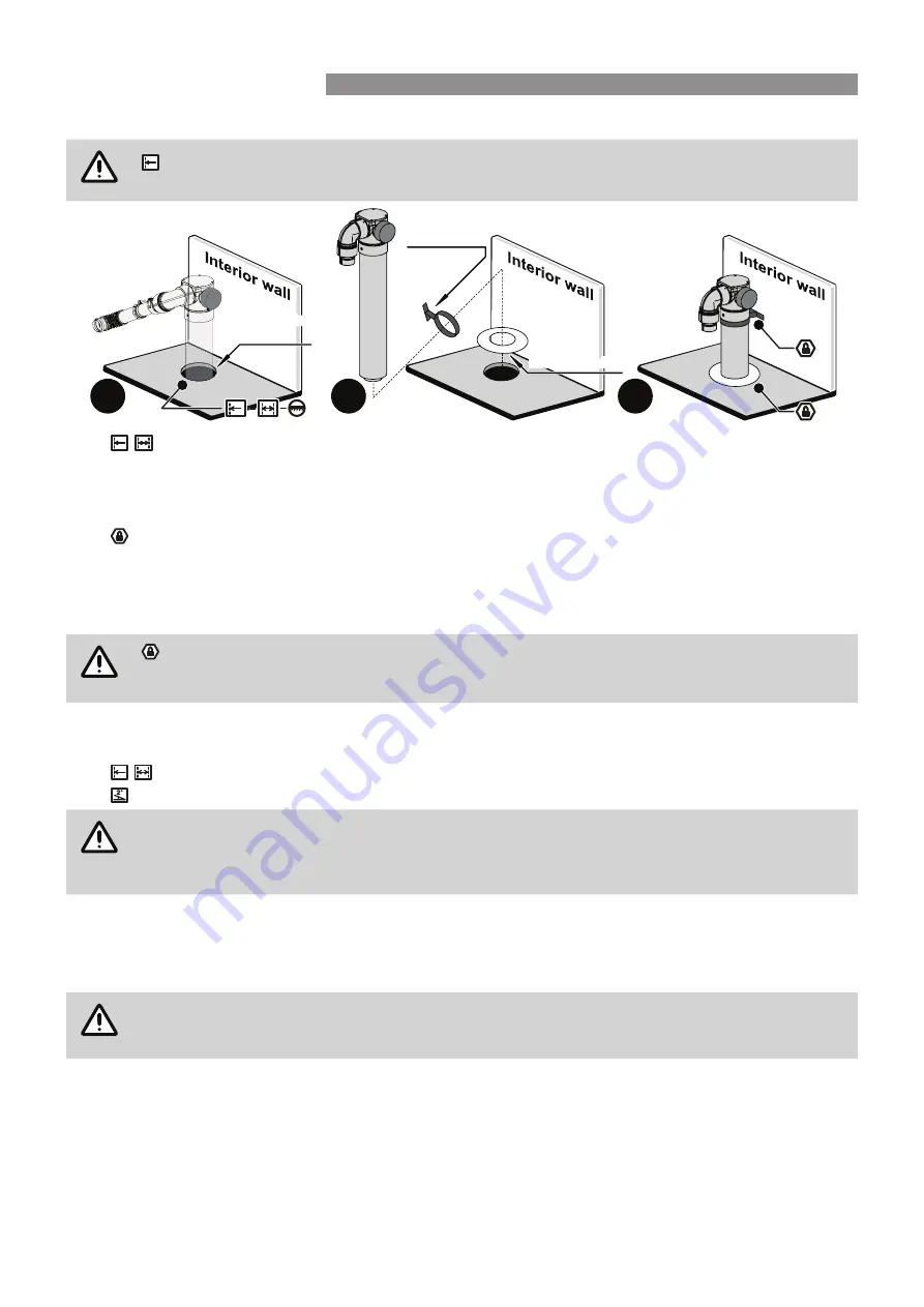
5.  Temporarily attach ESDFK to the flue outlet pipe from the rear of the heater. Align the flue in a vertical manner.  

CAUTION

 Ensure the flue components are positioned to have a minimum 25mm clearance from any 

sensor wires at the rear of the heater. 

6. 


 Mark the location of the flue floor penetration, then  cut an 100mm Ø hole through the floor. Ensure 

the hole edges are smooth.

7. 

Disconnect ESDFK form the heater. Pass ESDFK through both a stand off clip and the internal wall plate, 

then pass the assembly through the floor penetration.

8. 

 Secure ESDFK to the wall with a the stand off clip and fasten the internal wall plate in place to the floor.

9.  Prepare the horizontal section of the flue system located under floor by assembling connecting and securing 

ESPIPE900,  ESBEND  and  subsequent  ESPIPE900  lengths  as  required  in  accordance  with  the  relevant 

sections under "Component Assembly & Connection ~ ESBEND" on page 22 and “"Component Assembly 

& Connection ~ ESROOFCOWL" on page 23.

CAUTION

 The joint between ESDFK and ESPIPE900 

MUST

 be secured by a pop rivet or screw through 

the outer Co-Axial pipes and flue pipes are to be clipped to the wall using the stand off clips 

supplied or other suitable method. ESDFK and ESPIPE900 

DO NOT

 require cutting to be joined.

10.  Locate the heater in the desired position relative to the wall. 

DO NOT

 secure the heater at this stage.

11. 

If required create a wall penetration(s) in accordance with the section "Wall Penetrations" on page 10.


 The minimum diameter required for wall the penetration for ESPIPE900 is 80mm.

 Allow for a continuous 2° fall from the heater connection point from to the wall penetration.

CAUTION

Of special relevance to under floor installations is the requirement to have a minimum of 300mm 

clearance  between  the  flue  terminal  and  the  finished  ground  level.  It  is 

NOT

 permissible to 

excavate  a  hole  to  obtain  the  required  300mm  clearance,  unless  there  is  sufficient  drainage 

provision.

12.  Create the wall terminal in accordance with "Component Assembly & Connection ~ ESROOFCOWL" on page 

23.

13. 

Make the heater exhaust and combustion air hose connections in accordance with the section "Connecting 

Heater Exhaust" on page 28.

CAUTION

Air hose and heater exhaust connections at the Energysaver heater 

MUST

 be made and checked 

in accordance with these instructions. Improper connections may result in dangerous situations, 

for example, the dispersion of combustion products in the space being heated. 

14.  Install the remaining parts of the back cover kit and fasten the heater and back cover kit to the internal wall 

surface.

15.  Commission the heater in accordance with the manufacturer instructions supplied with the heater.

6

8

7

Internal wall plate

Internal wall plate

Floor Penetration

location

Floor Penetration

location

Stand off clip

INSTALLATION METHODS

Summary of Contents for ENERGYSAVER RHFE-308FTR

Page 1: ...o axial Flue System Installation Manual For Models RHFE 308FTR RHFE 309FT FT2 RHFE 556FTR FDT RHFE 557FTR RHFE 559FT FDT FT2 FDT2 RHFE 561FT FT2 RHFE 1004FT FDT RHFE 1005FT FDT FT2 FDT2 USE ONLYRINNAI GENUINE PARTS ...

Page 2: ... by Rinnai or otherwise are NOT compatible and MUST NOT be used Rinnai appliance warranty conditions may be voided if non Rinnai flue components are fitted ONLY an authorised person MUST install service and remove the Rinnai Energysaver space heater flue system This appliance must be installed in accordance with Manufacturer s Installation Instructions Current AS NZS 3000 AS NZS 3500 AS NZS 5601 L...

Page 3: ...Flue Installation Method 17 Under Floor Flue Installation Method 19 Cutting ESDFK ESPIPE900 ESROOFCOWL 21 Cutting components to achieve a desired length 21 Cutting components at a wall penetration 21 Component Assembly Connection ESPIPE900 21 Component Assembly Connection Wall Terminal ESDFK ESWTERM 22 Component Assembly Connection ESBEND 22 Component Assembly Connection ESCONDK 23 Component Assem...

Page 4: ...ulations and municipal building codes including local OH S requirements Flue components MUST be installed correctly by an appropriately licensed tradesperson The installation of gas water and electricity MUST conform to local regulations All dimensions referred to in these instructions are in millimetres unless otherwise specified These instructions ONLY apply to the Rinnai Energysaver co axial fl...

Page 5: ...fic installation OBSERVE CORRECT ORIENTATION Where specified ensure that components are installed with the correct vertical or horizontal orientation LUBRICATE Use the supplied container of silicon grease to lubricate components DO NOT use other lubricants as these may damage the flue components SECURE Where specified secure components with either installer provided or component supplied fixings D...

Page 6: ...ll or external corner 300 d From a gas meter M see 5 11 5 9 for vent terminal location of regulator see Table 6 6 for New Zealand requirements 1000 e From an electricity meter or fuse box P 500 500 f From a drain pipe or soil pipe 75 g Horizontally from any building structure or obstruction facing a terminal h From any other flue terminal cowl or combustion air intake 300 Appliances up to 150 MJ h...

Page 7: ...y it is recommended that a mat be placed in front of the appliance extending at least 750mm in front of it The flue terminal MUST BE positioned away from flammable materials In areas subject to heavy snowfall keep snow clear of flue terminal at all times DO NOT flue into natural draught flues or fireplaces DO NOT flue into other rooms roof spaces or into under floor spaces DO NOT Install the heate...

Page 8: ...he wall The lower end point of the arc iv will be the lower limit of the minimum horizontal and vertical centre of penetration G The upper end point of the arc v will the be the upper limit of the minimum horizontal and vertical centre of penetration G D E F iii vi vii G i ii 5 From the arc axis iii use the measurements F D E from Table 1 to draw an arc on the wall The lower end point of the arc v...

Page 9: ... appliance 426 465 750 550 545 760 930 930 ii Centre Line of appliance 213 233 375 275 273 380 465 465 iii Arc axis Axis point of the flue elbow No dimension A Horizontal dim Centre Line to arc centre 110 132 220 172 172 207 305 356 B Vertical dim base to arc centre 265 265 215 264 267 247 165 129 C Minimum horizontal limit of arc 150 150 240 200 200 240 325 376 D Minimum vertical limit of arc 270...

Page 10: ... Roof Cowl ESDFK ESPIPE900 ESBEND ESCONDK ESROOFCOWL Direct Flue Kit Co Axial Pipe 900mm Bend 2 x 45º Condensate Trap Wall Terminal Kit ESDFK ESPIPE900 ESBEND ESCONDK ESWTKIT2 IN WALL Components Option A Direct ESFKITIW Option B Offset ESFKITIW ESBEND In Wall Adaption Kit Co Axial Pipe 900mm x 4 Roof Cowl ESKIT03 ESPIPE900 ESROOFCOWL In Wall Adaption Kit Co Axial Pipe 900mm x 4 Bend 2 x 45º Roof C...

Page 11: ...ue terminal extension will count as one of the THREE 3 allowed bends of a flue run Note 4 Where stipulated a Minimum 2 fall is required to ensure correct drainage of condensation formed in the discharge flue IMPORTANT See Note 4 Min 2 fall towards the flue Terminal See Note 4 Min 2 fall towards the flue Terminal See Note 4 Min 2 fall towards the flue Terminal See Note 4 Min 2 fall towards the flue...

Page 12: ... Silicon Grease Wall Clip Grommet Use with 1004 1005 Drain Tube Co Ax Vertical Terminal Co Ax Pipe x4 Pipe Locating Spacer ESFKITIW Flue Kit In Wall ESWTKIT2 On Wall Terminal Kit ESWTERM Mounting Securing Screws 7mm x2 22mm x6 Flue Terminal External Wall Plate ESCONDK Condensate Trap Kit Condensation Trap Drain Tube ESPLATE External Wall Plate Mounting Securing Screws 22mm x3 7mm x2 ESPIPE900 Co A...

Page 13: ...k and 100mm to combustible surfaces such as plaster Allow for a continuous 2 fall from the heater connection point to the wall terminal 2 Slide the internal wall plate over the terminal end of the ESDFK pipe until it is nested on the raised ring of the flue transition 3 Pass the ESDFK through the internal wall penetration until the internal wall plate is flush with the wall 4 Create the wall termi...

Page 14: ...n the raised ring of the flue transition Join ESPIPE900 to ESDFK Fit additional lengths of ESPIPE900 as required CAUTION The joints between ESDFK and ESPIPE900 and any additional ESPIPE900 lengths MUST be secured by a pop rivet or screw through the outer Co Axial pipes to prevent accidental or erroneous dislodgement ESDFK and ESPIPE900 DO NOT require cutting to be joined Cutting of components is n...

Page 15: ...l these joints against ingress of dust and water ONLY use non acidic silicone sealant between the joints of outer PVC flue pipes and any mating aluminium components such as the condensate trap to secure and seal these joints against ingress of dust and water Silicone containing acetic acid vinegar or other acids as the curing agent may cause corrosion of aluminium components and MUST NOT be used S...

Page 16: ...ingress of dust and water ONLY use non acidic silicone sealant between the joints of outer PVC flue pipes and any mating aluminium components such as the condensate trap to secure and seal these joints against ingress of dust and water Silicone containing acetic acid vinegar or other acids as the curing agent may cause corrosion of aluminium components and MUST NOT be used Secure the vertical flue...

Page 17: ...o Axial pipes and flue pipes are to be clipped to the wall using the stand off clips supplied or other suitable method Steps for creating a Sideways flue installation are as follows 1 Using a drill remove the pop rivet used to fasten the straight flue pipe connection pipe to the flue transition of ESDFK and remove but DO NOT discard the straight flue pipe connection 2 Fit the elbowed flue pipe con...

Page 18: ... this stage 13 Fit additional lengths of ESPIPE900 as required CAUTION The joints between ESPIPE900 lengths MUST be secured by a pop rivet or screw through the outer Co Axial pipes and flue pipes are to be clipped to the wall using the stand off clips supplied or other suitable method ESDFK and ESPIPE900 DO NOT require cutting to be joined 14 Create the wall penetration s in accordance with the se...

Page 19: ...of ESDFK and remove but DO NOT discard the straight flue pipe connection 2 Fit the elbowed flue pipe connection supplied with the Back Cover kit to the flue transition pushing it fully home and then fasten in place with the grub screw supplied using an Allen key The grub screw terminates in a groove in the flue transition When fastened this prevents accidental dislodgement of the pipe connections ...

Page 20: ...d position relative to the wall DO NOT secure the heater at this stage 11 If required create a wall penetration s in accordance with the section Wall Penetrations on page 10 The minimum diameter required for wall the penetration for ESPIPE900 is 80mm Allow for a continuous 2 fall from the heater connection point from to the wall penetration CAUTION Of special relevance to under floor installations...

Page 21: ...4 Ensure all burrs and swarf are removed from all cut ends Cutting components at a wall penetration 1 Measure and mark off the outer pipe at a point flush with the surface of the wall penetrated CC PLUS an additional 50mm DD CAUTION The minimum length ZZ of ESDFK when measured from the back plate of the casting MUST NOT be less than 300mm when joining to other components 2 Cut the outer pipe to th...

Page 22: ...ntal holes and the two 7mm screws provided 2 Carefully cut through the outer and inner pipes of the flue protrusion as close to the external wall plate as possible Take care to avoid cutting the external wall plate and keep the cuts of both internal and external pipes as parallel as possible All burrs and swarf are to removed from all cut ends 3 Align the arrows of the metal mushroom flue terminal...

Page 23: ...ve the correct orientation of ESCONDK The arrow symbol MUST point away from the heater towards the termination of the flue system Lubricate all inner pipe O Rings with the silicone grease provided CAUTION A condensate drain MUST be connected for all In Wall installations for details see Connecting Condensate Drain Tube To Heater on page 30 COMPONENT ASSEMBLY CONNECTION ESROOFCOWL CAUTION Both the ...

Page 24: ...aining acetic acid characteristically having a vinegar odour as the curing agent or other acids may cause corrosion of aluminium components and MUST NOT be used Insert the cut section of inner pipe into the female socket of the preceding component ensuring that it is fully home Then insert the cut section of outer pipe into the female socket of the preceding component ensuring it is also fully hom...

Page 25: ...H 2 Remove the screw from the front of the transition casting retain and DO NOT discard and slide the wall spacer plate over the transition casting so that the folded tab is facing both down and to the rear Using the screw removed from the front of the transition casting attach the mounting strip across the front of the transition casting Lubricate the O Ring of the condensate trap and attach this...

Page 26: ...ng towards the heater fit the required lengths of ESPIPE900 to reach but not pass through the top plate lubricating the O Rings of each additional ESPIPE900 length before fitting When this point is reached secure the top plate bracket over the hole in the top plate 5 Continue Flueing to the termination point and fit an ESROOFCOWL observing the clearances and regulations refer to page 4 To avoid ob...

Page 27: ... WARNING AT NO TIME MUST THE AIR INTAKE HOSE BE CUT OR SHORTENED 7 7 8 Air intake hose Air intake hose Move the right hand vermin plate along the hose until it is flush against the wall then secure in place with three of the nine screws provided 8 Screw the left hand vermin plate to the right hand vermin plate when overlapped correctly the holes in both plates will be aligned using three of the ni...

Page 28: ...fit to the exhaust pipe of the heater Push the exhaust pipe fully home so that the end of the exhaust connection and the collar of the exhaust pipe are fully mated IMPORTANT For 1004 and 1005 models an additional flue component Flue Adaptor is supplied with the heater which steps down the larger diameter heater exhaust to that used by the exhaust connection on the flue system 2 Attach the flue loc...

Page 29: ...whilst the finger tabs are secured around the collar of the fixed flue spigot applies to models 556 557 1004 CAUTION This joint MUST be properly secured in accordance with these instructions using the flue lock provided when applicable If the joint is not properly secured products of combustion could disperse into the room being heated Which may result in a dangerous condition CONNECTING COMBUSTIO...

Page 30: ...innai part number 90180944 2 90 120 RHFE 308FTR 75 120 RHFE 309FT FT2 65 80 RHFE 556FTR FDT 115 120 RHFE 557FTR RHFE 561FT FT2 80 RHFE 559FT FDT FT2 FDT2 115 Dim B Dim A Dim A Dim B RHFE 1004FTR FDT 510mm 135mm 500mm 100mm Heat Shields Heat Shield Heat Shield Heat Shield Heat Shield Heat Shield Back panel Back panel Back panel Back panel Back panel Back panel RHFE 1005FT FDT FT2 FDT2 Drill the low...

Page 31: ...Rinnai 31 ES_FIM NOTES ...

Page 32: ...or public phones For further information visit www rinnai com au or email enquiry rinnai com au Rinnai has a Service and Spare Parts network with personnel who are fully trained and equipped to give the best service on your Rinnai appliance If your appliance requires service please call our National Help Line Rinnai recommends that this appliance be serviced every 2 years With our policy of contin...

Reviews: