20170392
26
GB
Installation
6.14
Calibration of the thermal relay
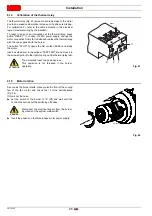
The thermal relay (Fig. 23) serves to avoid damage to the motor
due to an excessive absorption increase or if a phase is missing.
For calibration 2), refer to the table indicated in the electrical
layout (electrical wiring by the installer).
To reset, in case of an intervention of the thermal relay, press
button "RESET" 1). In case of 230V power supply, change the
motor connection from star to delta and replace the thermal relay
with the one supplied with the burner.
The button “STOP” 3) opens the NC contact (95-96) and stops
the motor.
Insert a screwdriver in the window “TEST/TRIP” 4) and move it in
the arrow direction (to the right) to carry out the thermal relay test.
6.15
Motor rotation
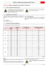
As soon as the burner starts, place yourself in front of the cooling
fan of the fan motor and check that it turns anticlockwise
(Fig. 24).
If this is not the case:
put the switch of the burner to “0” (off) and wait until the
control box carries out the switching off phase.
Invert the phases on the three-phase motor power supply.
ATTENTION
The automatic reset can be dangerous.
This operation is not foreseen in the burner
operation.
1
2
3
MAN
AUT
O
STOP
NO
98
97
96
95
RESET
NC
4
TEST/TRIP
Fig. 23
D8685
DANGER
Disconnect the electrical supply from the burner
by means of the system main switch.
Fig. 24
20162749
Summary of Contents for PRESS 140 P/N
Page 2: ...Translation of the original instructions...
Page 57: ...55 20170392 GB Appendix Electrical panel layout 0 1 2 2 2 0 DIRECT START UP...
Page 58: ...20170392 56 GB Appendix Electrical panel layout 0 1 1 1 STAR TRIANGLE START UP...
Page 59: ...57 20170392 GB Appendix Electrical panel layout 0 1 0...

