20170392
12
GB
Technical description of the burner
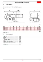
5.7
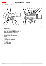
Burner description
1
Suction connection
2
Pump pressure regulator
3
Return connection
4
Pressure gauge connection (PRESS 140 - G 1/8)
Pressure gauge connection (PRESS 200-300-450 - G 1/4)
5
Vacuometer connection (PRESS 140 - G 1/2)
Vacuometer connection (PRESS 200-300-450 - G 1/4)
6
Maximum temperature thermostat
7
Minimum temperature thermostat
8
Control box reset button with lockout signal
9
Fan motor
10 Setting thermostat
11 Air adjustment cam
12 Servomotor
13 Modulator (only for modulating units)
14 Nozzle rod opening magnet
15 Pressure adjustment eccentric on return line
16 Pressure switch
17 Return pressure gauge
18 Delivery pressure gauge
19 Combustion head adjustment screw
20 Filter
1 2
3
4
5
6
7
8
14
19
18
20
17
16
15
13
10
12
11
9
Fig. 4
20172325
Summary of Contents for PRESS 140 P/N
Page 2: ...Translation of the original instructions...
Page 57: ...55 20170392 GB Appendix Electrical panel layout 0 1 2 2 2 0 DIRECT START UP...
Page 58: ...20170392 56 GB Appendix Electrical panel layout 0 1 1 1 STAR TRIANGLE START UP...
Page 59: ...57 20170392 GB Appendix Electrical panel layout 0 1 0...


