65
20170392
GB
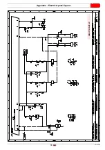
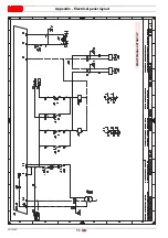
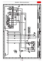
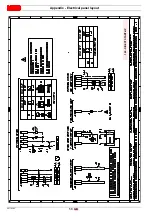
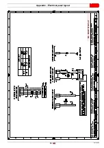
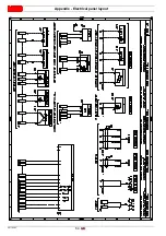
Appendix - Electrical panel layout
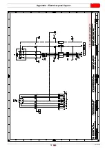
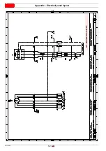
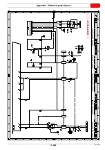
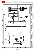
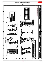
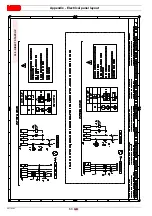
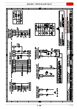
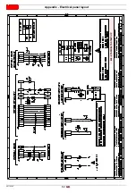
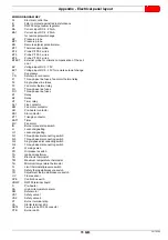
WIRING DIAGRAM KEY
A1
Electrical control box
B
Filter to protect against radio disturbance
B1
RWF50 output power regulator
BA
Current input DC 4...20mA
BA1
Current input DC 4...20mA
for remote setpoint change
BP
Pressure probe
BP1
Pressure probe
BR
Remote setpoint potentiometer
BT1
Thermocouple probe
BT2
Probe Pt100, 2 wires
BT3
Probe Pt100, 3 wires
BT4
Probe Pt100, 3 wires
BTEXT
External probe for climatic compensation of the set-
point
BV
Voltage input DC 0...10V
BV1
Voltage input DC 0...10V for remote setpoint change
C
Suppressor
CN
Servomotor connector
F1
Three-phase line fuses, fan motor thermal relay
F2
Single-phase line fuses
F3
Fan motor thermal relay
FU
Three-phase line fuses
FU1
Three-phase line fuses
K1
Relay
K2
Relay
KT
Timer relay
KL1
Line contactor
KM
Fan motor contactor
KR
Pre-heater contactor
KS1
Star contactor
KT1
Triangle contactor
KST1
Timer
MV
Fan motor
IN
Burner manual stop switch
H
Lockout signalling
H1
Lockout signalling
Q1
Three-phase disconnecting switch
Q3
Three-phase disconnecting switch
Q2
Single-phase disconnecting switch
Q4
Three-phase disconnecting switch
VF
Working valve
PO
Oil pressure switch
TA
Ignition transformer
TE
Electronic thermostat
TM
Maximum temperature thermostat
Tm
Minimum temperature thermostat
TL
Limit thermostat/pressure switch
TS
Safety thermostat/pressure switch
TR
Adjustment thermostat/pressure switch
UV
Flame sensor
XPE
Control box earth
XRWF
RWF50 terminal board
S
Pre-heater
SA
High oil temperature alarm
SM
Servomotor
VS1
Safety valve 1
VS2
Safety valve 2
X1
Burner terminal strip
XA
Starter terminal strip
XBT4
3-wire probe Pt100 connector
XTB
Burner earth
Summary of Contents for PRESS 140 P/N
Page 2: ...Translation of the original instructions...
Page 57: ...55 20170392 GB Appendix Electrical panel layout 0 1 2 2 2 0 DIRECT START UP...
Page 58: ...20170392 56 GB Appendix Electrical panel layout 0 1 1 1 STAR TRIANGLE START UP...
Page 59: ...57 20170392 GB Appendix Electrical panel layout 0 1 0...

