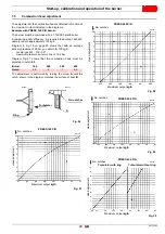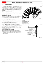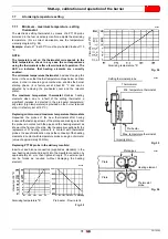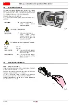
17
20170392
GB
Installation
6.4
Operating position
6.5
Boiler plate
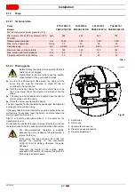
Pierce the closing plate of the combustion chamber, as in
(Fig. 10). The position of the threaded holes can be marked using
the thermal insulation screen supplied with the burner.
For the combustion head protrusion follow the indications
provided by the boiler manufacturer.
Tab. F
6.6
Blast tube length
The length of the blast tube must be selected according to the
indications provided by the manufacturer of the boiler, and in any
case it must be greater than the thickness of the boiler door
complete with its fettling.
Tab. G
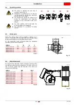
ATTENTION
The burner is designed to work only in
positions
1
and
4
(Fig. 9).
Installation
1
is preferable, as it is the only
one that allows the maintenance operations
as described in this manual.
The installation
4
permits the operation but
makes the maintenance and inspection
operations of the combustion head more
difficult.
DANGER
Any other position could compromise the
correct operation of the appliance.
The installation
5
is prohibited for safety
reasons.
Fig. 9
2
3
4
5
1
20172679
MODEL
L
M
N
P
PRESS 140 P/N
260
230
M 14
225
PRESS 200 P/N
260
-
M 16
255
PRESS 300 P/N
-
260
M 18
300
PRESS 450 P/N
-
310
M 20
350
Fig. 10
S9890
MODEL
MIN
MAX
PRESS 140 P/N TC
180
300
PRESS 200 P/N TC
200
340
PRESS 300 P/N TC
200
350
PRESS 450 P/N TC
250
400
PRESS 140 P/N TL
290
410
PRESS 200 P/N TL
310
450
PRESS 300 P/N TL
330
480
PRESS 450 P/N TL
380
530
20172681
MIN
MAX
Fig. 11
Summary of Contents for PRESS 140 P/N
Page 2: ...Translation of the original instructions...
Page 57: ...55 20170392 GB Appendix Electrical panel layout 0 1 2 2 2 0 DIRECT START UP...
Page 58: ...20170392 56 GB Appendix Electrical panel layout 0 1 1 1 STAR TRIANGLE START UP...
Page 59: ...57 20170392 GB Appendix Electrical panel layout 0 1 0...

