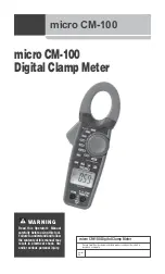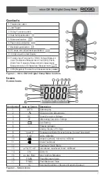
micro CM-100 Digital Clamp Meter
10
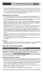
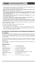
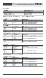
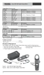
Do not connect to voltages that exceed 600 VAC or VDC relative to earth ground.
This may damage the meter and expose the operator to a shock hazard.
When using the probes, keep your fingers behind the finger guards on the
probes.
This reduces the risk of electric shock.
Never ground yourself when taking electrical measurements.
Do not touch ex-
posed metal pipes, outlets, fixtures, etc., which might be at ground potential. Keep your
body isolated from ground using appropriate methods.
Use extreme caution when working near bare conductors and bus bars.
Acci-
dental contact with conductors could result in electrical shock.
1. Check for an appropriate work area as indicated in the
General Safety section.
2. Inspect the work to be done and confirm that you have correct equipment for the ap-
plication. See the
Specifications section for range, accuracy and other information.
• To select a function, turn the rotary function switch to the appropriate position.
• Select the proper function and range for your measurement.
• Determine the voltage to be measured. Do not apply more than the rated voltage,
as marked on the meter, between terminals or between any terminal and earth
ground.
• Check the clamps for full closure. Do not use the meter if the clamps do not op-
erate properly.
• Turn the function switch to the OFF position after inspection.
3. Make sure all equipment being used has been properly inspected.
4. Use correct accessories for the application. Select the proper terminals, function,
and range for all measurements.
5. When making electrical connections, connect the common test lead (black) before
connecting the live test lead (red); when disconnecting, disconnect the live test lead
(red) before disconnecting the common test lead (black).
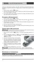
6. If “OL” appears in the display during a measurement, the value exceeds the range
you have selected, change to a higher range. On some low DC and AC voltage
ranges, with the test leads not connected to a device, the display may show a ran-
dom, changing reading. This is normal and is caused by the high-input sensitivity. The
reading will stabilize and give a proper measurement when connected to the circuit.
7. Always turn the function switch to the OFF position when the meter is not in use. The
meter will automatically shut OFF if not used for 20 minutes.
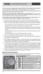
Rotary Function Switch
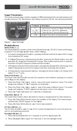
The Rotary Function switch permits the user to select a measurement function by posi-
tioning the rotary switch to one of the icons around its perimeter.
Figure 6 – Rotary Function Switch
Switch Position Function
DC/AC Current Measurement up to 1000 A
DC/AC Current Measurement up to 400 A
DC/AC Current Measurement up to 40 A
Continuity/Diode Test & Resistance Measurement
Voltage and Frequency Measurement
Capacitance Measurement
Temperature Measurement in °C or °F
Switch OFF the Clamp Meter
Summary of Contents for Micro CM-100
Page 38: ...Multim tre num rique pinces micro CM 100 36...
Page 58: ...Mult metro de Mordaza Digital micro CM 100 56...
Page 98: ...micro CM 100 Digitale stroomtang 96...
Page 118: ...Misuratore digitale a pinza micro CM 100 116...
Page 138: ...Amper metro Digital CM 100 micro 136...
Page 158: ...micro CM 100 Digital t ngmultimeter 156...
Page 232: ...Cyfrowy miernik c gowy micro CM 100 230...
Page 288: ...Cle te de curent digital micro CM 100 286...
Page 308: ...micro CM 100 Digit lis lakatfog s multim ter 306...
Page 309: ...micro CM 100 micro CM 100 micro CM 100...
Page 311: ...micro CM 100 309 t t t t t...
Page 312: ...micro CM 100 310 t t t t t t t t t t t RIDGID micro CM 100...
Page 320: ...micro CM 100 318 5 micro CM 100 30 V AC RMS 42 V AC 60 V DC 600 VAC VDC 1 2 t t t t t 0 3 4 5...
Page 324: ...micro CM 100 322 3 4 5 2 3 COM V CAP TEMP Hz 4 5 6 t 0 t 0 t 2 3 COM V CAP TEMP Hz 4 5 6 35...
Page 328: ...micro CM 100 326 RIDGID...
Page 384: ...micro CM 100 digitalna strujna kle ta 382...
Page 385: ...micro CM 100 micro CM 100 micro CM 100...
Page 387: ...micro CM 100 385 t t t t t...
Page 388: ...micro CM 100 386 t t t t t t t y e t t t t...
Page 396: ...micro CM 100 394 5 1 2 3 9 NEDA 1604 IEC 6F22 6LR61 4 1 2 3 t t t t 4 t t 5...
Page 397: ...micro CM 100 395 micro CM 100 30 42 60 DC 600 1 2 t t t t t OFF 3 4 5...
Page 398: ...micro CM 100 396 6 OL 7 OFF 20 1000 400 40 C F COM V CAP TEMP Hz COM 7 6...
Page 400: ...micro CM 100 398 1 2 3 COM V CAP TEMP Hz 4 0 5 DC AC V 8 1 2 3 4...
Page 401: ...micro CM 100 399 5 1 2 COM V CAP TEMP Hz 3 4 5 1 2 3 COM V CAP TEMP Hz 4 5 6 t OL t 0 o t o...
Page 403: ...micro CM 100 401 9 3 4 30 5 6 C F t t RIDGID RIDGID micro CM 100 44748 44758 K...
Page 405: ...micro CM 100 403 RIDGID...
Page 406: ...micro CM 100 404...
Page 427: ......

