On Product Icons
This equipment is used to make electrical measurements. Incorrect use or im-
proper application may result in incorrect or inaccurate measurements. Selection of ap-
propriate measurement methods for the conditions is the responsibility of the user.
FCC Statement
This equipment has been tested and found to comply with the limits for a Class B digi-
tal device, pursuant to part 15 of the FCC Rules. These limits are designed to provide
reasonable protection against harmful interference in a residential installation.
This equipment generates, uses, and can radiate radio frequency energy and, if not in-
stalled and used in accordance with the instructions, may cause harmful interference to
radio communications.
However, there is no guarantee that interference will not occur in a particular installation.
If this equipment does cause harmful interference to radio or television reception, which
can be determined by turning the equipment off and on, the user is encouraged to try to
correct the interference by one or more of the following measures:
• Reorient or relocate the receiving antenna.
• Increase the separation between the equipment and receiver.
• Consult the dealer or an experienced radio/TV technician for help.
Electromagnetic Compatibility (EMC)
The term electromagnetic compatibility is taken to mean the capability of the product to
function smoothly in an environment where electromagnetic radiation and electrostatic
discharges are present and without causing electromagnetic interference to other equip-
ment.
The RIDGID micro CM-100 Digital Clamp Meter conforms to all applicable
EMC standards. However, the possibility of it causing interference in other devices can-
not be precluded.
Changing/Installing Batteries
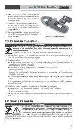
The RIDGID micro CM-100 Digital Clamp Meter is supplied without the battery installed.
When the low battery [ ] icon appears on the display screen, replace the battery. Op-
erating the clamp meter with a low battery can cause incorrect readings. Remove the bat-
tery prior to long-term storage to avoid battery leakage.
1. Switch OFF the device and disconnect test leads.
micro CM-100 Digital Clamp Meter
8
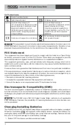
Double Insulation Symbol
Earth Ground Symbol
9V Battery Symbol
CAT III
IEC Overvoltage Category III
CAT II
IEC Overvoltage Category II
CAT III equipment is designed to protect
CAT II equipment is designed to protect
against transients in equipment in fixed
against transients from energy-
equipment installations, such as
consuming equipment supplied from
distribution panels, feeders and short
the fixed installation, such as TVs, PCs
branch circuits, and lighting systems
portable tools, and other household
in large buildings.
appliances.
Do not dispose of electrical equipment
Conforms to European Union directives.
with household waste!
NOTICE
NOTICE
Summary of Contents for Micro CM-100
Page 38: ...Multim tre num rique pinces micro CM 100 36...
Page 58: ...Mult metro de Mordaza Digital micro CM 100 56...
Page 98: ...micro CM 100 Digitale stroomtang 96...
Page 118: ...Misuratore digitale a pinza micro CM 100 116...
Page 138: ...Amper metro Digital CM 100 micro 136...
Page 158: ...micro CM 100 Digital t ngmultimeter 156...
Page 232: ...Cyfrowy miernik c gowy micro CM 100 230...
Page 288: ...Cle te de curent digital micro CM 100 286...
Page 308: ...micro CM 100 Digit lis lakatfog s multim ter 306...
Page 309: ...micro CM 100 micro CM 100 micro CM 100...
Page 311: ...micro CM 100 309 t t t t t...
Page 312: ...micro CM 100 310 t t t t t t t t t t t RIDGID micro CM 100...
Page 320: ...micro CM 100 318 5 micro CM 100 30 V AC RMS 42 V AC 60 V DC 600 VAC VDC 1 2 t t t t t 0 3 4 5...
Page 324: ...micro CM 100 322 3 4 5 2 3 COM V CAP TEMP Hz 4 5 6 t 0 t 0 t 2 3 COM V CAP TEMP Hz 4 5 6 35...
Page 328: ...micro CM 100 326 RIDGID...
Page 384: ...micro CM 100 digitalna strujna kle ta 382...
Page 385: ...micro CM 100 micro CM 100 micro CM 100...
Page 387: ...micro CM 100 385 t t t t t...
Page 388: ...micro CM 100 386 t t t t t t t y e t t t t...
Page 396: ...micro CM 100 394 5 1 2 3 9 NEDA 1604 IEC 6F22 6LR61 4 1 2 3 t t t t 4 t t 5...
Page 397: ...micro CM 100 395 micro CM 100 30 42 60 DC 600 1 2 t t t t t OFF 3 4 5...
Page 398: ...micro CM 100 396 6 OL 7 OFF 20 1000 400 40 C F COM V CAP TEMP Hz COM 7 6...
Page 400: ...micro CM 100 398 1 2 3 COM V CAP TEMP Hz 4 0 5 DC AC V 8 1 2 3 4...
Page 401: ...micro CM 100 399 5 1 2 COM V CAP TEMP Hz 3 4 5 1 2 3 COM V CAP TEMP Hz 4 5 6 t OL t 0 o t o...
Page 403: ...micro CM 100 401 9 3 4 30 5 6 C F t t RIDGID RIDGID micro CM 100 44748 44758 K...
Page 405: ...micro CM 100 403 RIDGID...
Page 406: ...micro CM 100 404...
Page 427: ......

