RIDGID 535 Auto Chuck Manual Download Page 8

999-998-086.10_REV. C

8

535 Manual Chuck/535 Auto Chuck Threading Machines
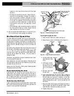
the die head. See 

Die Head Set-Up and Use

section

for details.

7. Swing the cutter, reamer and die head up away from

the operator. Make sure they are stable and will not fall
in the work area.

8. If pipe will extend past the chip tray in the front of the

machine or more than 4' (1,2 m) out of the rear of the
machine, use pipe stands to support the pipe and pre-
vent the pipe and threading machine from tipping or
falling.  Place  the  pipe  stands  in  line  with  machine
chucks, approximately 1/3 of distance from end of the
pipe to the machine. Longer pipe may need more than
one  pipe  stand.  Only  use  pipe  stands  designed  for
this  purpose.  Improper  pipe  supports  or  supporting
the pipe by hand can cause tipping or entanglement
injuries.

9. Restrict  access  or  set-up  guards  or  barricades  to

create a minimum of 3' (1 m) clearance around the
threading machine and pipe. This helps prevent non-
operators from contacting the machine or pipe and
reduces the risk of tipping or entanglement.

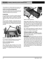
10. Position the foot switch as shown in 

Figure 17

, to allow

a proper operating position.

11. Check the level of RIDGID Thread Cutting Oil. Remove

the chip tray and oil pan liner; see that the filter screen
assembly  is  fully  submerged  in  oil.  See 

Oil  System

Maintenance

.

12. With the REV/OFF/FOR Switch in OFF position, run the

cord  along  a  clear  path. With  dry  hands,  plug  the
power  cord  into  properly  grounded  outlet.  Keep  all
connections dry and off the ground. If the power cord is
not long enough use an extension cord that:

• Is in good condition.

• Has a three-prong plug like on the threading machine.

• Is rated for outdoor use and contains a W or W-A in

the cord designation (e.g. SOW).

• Has sufficient wire size. For extension cords up to 50'

(15.2 m) long use 16 AWG (1.5 mm

2

) or heavier. For

extension  cords  50'-100'  (15.2  m  -  30.5  m)  long
use 14 AWG (2.5 mm

2

) or heavier.

13. Check  the  threading  machine  for  proper  operation.

With hands clear of moving parts:

• Move the REV/OFF/FOR (2/0/1) Switch to the FOR

(1) position. Press and release the foot switch. Chuck
should rotate counter-clockwise when viewed from
the carriage end 

(see Figure 22)

. Repeat for REV

position – chuck should rotate clockwise. If the thread-
ing machine does not rotate in the correct direction,
or the foot switch does not control the machine

Machine and Work Area Set-up

WARNING

Set  up  the  Threading  Machine  and  the  work  area
according to these procedures to reduce the risk of
injury from electric shock, machine tipping, entan-
glement,  crushing  and  other  causes,  and  to  help
prevent threading machine damage.

Secure machine to stable stand or bench. Properly
support  pipe.  This  will  reduce  the  risk  of  falling
pipe, tipping and serious injury.

do not use the Threading Machines without a prop-
erly operating foot switch. A foot switch provides
better control by letting you shut off the machine
motor by removing your foot.

1. Check work area for:

• Adequate lighting.
• Flammable liquids, vapors or dust that may ignite. If

present, do not work in area until source is identified,
removed or corrected, and area is completely ven-
tilated. The  threading  machine  is  not  explosion
proof and can cause sparks.

• Clear, level, stable and dry place for all equipment

and operator.

• Good ventilation. Do not use extensively in small,

enclosed areas.

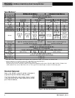
• Properly  grounded  electrical  outlet  of  the  correct

voltage. Check the machine serial plate for required
voltage. A  three-prong  or  GFCI  outlet  may  not  be
properly grounded. If in doubt, have outlet inspected
by a licensed electrician.

2. Inspect  the  pipe  to  be  threaded  and  associated  fit-

tings.  Determine  the  correct  equipment  for  the  job,

see Specifications

. Do not use to thread anything oth -

er than straight stock. Do not thread pipe with fittings or
other  attachments. This  increases  the  risk  of  entan-
glement.

3. Transport  equipment  to  work  area.  See 

Preparing

Machine for Transport 

for information.

4. Confirm equipment to be used has been properly in -

spected and assembled.

5. Confirm that the REV/OFF/FOR Switch is in the OFF

position.

6. Check that the correct dies are in the die head and are

properly set. If needed, install and/or adjust the dies in

Summary of Contents for 535 Auto Chuck

Page 1: ...535 Manual Chuck 535 Auto Chuck Threading Machines Threading MachineManual 99 Washington Street Melrose MA 02176 Phone 781 665 1400 Toll Free 1 800 517 8431 Visit us at www TestEquipmentDepot com...

Page 2: ...you to potential personal injury hazards Obey all safety messages that follow this symbol to avoid possible injury or death DANGER indicates a hazardous situation which if not avoided will result in...

Page 3: ...ned from frequent use of tools allow you to become complacent and ignore tool safety principles A careless action can cause severe injury within a fraction of a second 535 Manual Chuck 535 Auto Chuck...

Page 4: ...ding Machines to reduce the risk of electrical shock or other serious injury SAVe ALL WARNINGS ANd INSTRuCTIoNS FoR FuTuRe ReFeReNCe Keep this manual with machine for use by the operator Threading Mac...

Page 5: ...l Chuck 535 Auto Chuck Threading Machines Chuck Handwheel Die Head No 820 Cutter No 341 Reamer Chip Tray REV OFF FOR 2 0 1 Switch Foot Switch Carriage Handwheel Length Gauge Die Head No 820 Cutter No...

Page 6: ...Centering Device Cam Action rotates with Chuck Automatic Centering only Die Heads See RIDGID Catalog for available Die Heads Cutter Model 820 1 8 2 Full Floating Self Centering Cutter Reamer Model 34...

Page 7: ...uipment being used per its instructions to make sure it is functioning properly 999 998 086 10_REV C 7 Selection of appropriate materials and instal lation joining and forming methods is the responsib...

Page 8: ...rts Move the REV OFF FOR 2 0 1 Switch to the FOR 1 position Press and release the foot switch Chuck should rotate counter clockwise when viewed from the carriage end see Figure 22 Repeat for REV posit...

Page 9: ...your die head Always cut a test thread to confirm proper thread size after changing adjusting the Dies Removing Installing die Head Insert remove Die Head Post into mating hole in car riage When full...

Page 10: ...ead Size 1 Install the die head move the die head into threading position 2 Loosen clamp lever 3 Start with link index mark aligned with desired size mark on size bar On Bolt die heads set link mark a...

Page 11: ...engagement or UNDER smaller thread dia meter more turns of fitting en gagement markings 5 Tighten clamp lever Trigger Slide Adjustment Position the Trigger Slide for the size of pipe being thread ed...

Page 12: ...k process and the foot switch do not operate with more than one person In case of entanglement the operator must be in control of the foot switch Follow operating instructions to reduce the risk of in...

Page 13: ...used for cutting and reaming Threading Speed Selection Up to 36 RPM Suitable for threading up to 2 pipe bolt threading high torque applications like stainless steel and high hardness material 46 RPM S...

Page 14: ...o the FOR position 4 With both hands grasp the pipe cutter feed handle 5 Depress the foot switch 6 Tighten the feed screw handle one half turn per rota tion of the pipe until the pipe is cut More aggr...

Page 15: ...verse REV with dies engaged 9 Remove foot from the foot switch 10 Move the REV OFF FOR Switch to the OFF posi tion 11 Turn the carriage handwheel to move the die head past the end of the pipe Raise th...

Page 16: ...the OFF 0 position Figure 24 LH or RH Oil Flow Selector Left hand threading requires the chuck jaws to grip the pipe during REV rotation of the machine a Make sure that the REV OFF FOR 2 0 1 switch i...

Page 17: ...If issues such as thread tearing waviness thin threads or pipe out of roundness are found the thread may not seal Refer to the Troubleshooting Chart for help in diagnosing these issues 3 Inspect the s...

Page 18: ...mend that they be added Contact Ridge Tool Technical Service Department at rtctechservices emerson com or 800 519 3456 regard ing a retrofit policy If the jaw inserts do not grip and need to be cleane...

Page 19: ...to hold pipe or rod during operation flip jaws to unused side or replace entire set of jaws 1 Loosen all three front cover mounting screws and remove the front cover Mounting screws are retained to fr...

Page 20: ...confirm that the belt is properly tensioned Tighten the 4 fasteners that hold the motor to the motor bracket optional equipment WARNING To reduce the risk of serious injury only use equip ment specif...

Page 21: ...tions on the threading oil label and Safety Data Sheet SDS Specific information about RIDGID Thread Cutting Oils including Hazard Identification First Aid Fire Fighting Accidental Release Measures Han...

Page 22: ...t tight on pipe 535A Brake assembly not properly adjusted 535A Replace dies Only use RIDGID Thread Cutting Oil Replace the RIDGID Thread Cutting Oil Clean chips dirt or other foreign material from bet...

Page 23: ...RIDGID logo are registered trademarks of Emerson Electric Co or RIDGID Inc in the U S and other countries All other trademarks belong to their respective holders 99 Washington Street Melrose MA 02176...

Reviews: