


999-998-086.10_REV. C
20
535 Manual Chuck/535 Auto Chuck Threading Machines
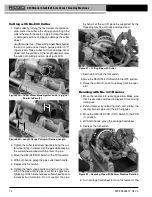
2. Place insert sideways on locking pin and press down
as far as possible
(Figure 33)
.
3. Hold insert down firmly, and with screwdriver, turn so
teeth face up.
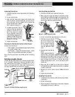
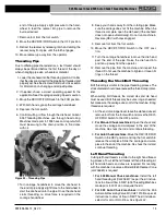
Replacing Carbon Brushes (universal
Motor units)
Check motor brushes every 6 months. Replace when worn
to less than ½".
1. Unplug the machine from power source.
2. Remove the top cover
.
Figure 34 – Removing Motor Cover/Changing Brushes
3. Unscrew brush caps (both top and bottom of motor).
Remove and inspect brushes. Replace when worn
to less than ½". Inspect the commutator for wear. If
excessively worn, have machine serviced.
4. Re-install brushes/install new brushes. Reassemble
unit. Install all covers before operating machine.
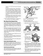
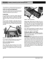
V-Belt Tension/Replacement (Induction
Motor units)
Figure 35 – Belt Tensioning
When lubricating the grease fittings, check v-belt tension.
Apply moderate finger force (about 4 pounds (2 kg)) to
the midpoint of the belt. Belt should deflect approximately
1/8" (3mm)
(Figure 35)
.
1. Loosen the four fasteners that hold the motor to the
motor bracket.
2. If changing the belt, loosen the belt tensioner. Slide the
motor toward the pulley. Remove and replace the
belt.
3. Tighten the belt tensioner.
4. Make sure the pulleys are aligned and confirm that the
belt is properly tensioned. Tighten the 4 fasteners
that hold the motor to the motor bracket.
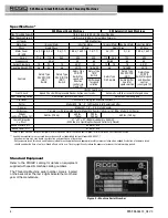
optional equipment
WARNING
To reduce the risk of serious injury, only use equip-
ment specifically designed and recommended for use
with the RIdGId 535 Manual Chuck/535 Auto Chuck
Threading Machines.
For a complete listing of RIdGId equipment avail-
able for the 535 Manual Chuck/535 Auto Chuck
Catalog
No.
Model Description
42365
341
Reamer
42390
820
Wheel-Type Cutter
41620
–
Gearhead Motor Grease
Die Heads
42485
4U
Die Head Rack
42490
6U
Die Head Rack
97065
811A
Quick-Opening Die Head NPT RH
97075
815A
Self-Opening Die Head NPT RH
23282
842
Quick-Opening Die Head NPT LH
97070
811A
Quick-Opening Die Head BSPT RH
97080
815A
Self-Opening Die Head BSPT RH
97045
531
Quick-Opening Bolt Die Head RH/LH ¼" to 1"
97050
532
Quick-Opening Bolt Die Head RH/LH 1 1/8" to 2"
84537
816
Semi-Automatic Die Head 1/8" to ¾"
84532
817
Semi-Automatic Die Head 1" to 2"
Threader Stands
92457
100A
Universal Leg & Tray Stand
92462
150A
Universal Wheel & Tray Stand
92467
200A
Universal Wheel & Cabinet Stand
Nipple Chucks
51005
819
Nipple Chuck ½" to 2" NPT
68160
819
Nipple Chuck ½" to 2" BSPT
For 535 Manual Chuck Machines Only
96517
MJ-1
535 Left Hand Threading Kit
97365
-
Jaw Inserts for Coated Pipe
For 535 Auto Chuck Machines Only
12138
535A
Left Hand Threading Kit
94017
–
Front Jaw
35867
839
Adapter Kit for 819 Nipple Chuck
Brush
Cap
Belt
Tensioner
Motor
Fasteners
V-Belt


