RIDGID 535 Auto Chuck Manual Download Page 18

999-998-086.10_REV. C

18

535 Manual Chuck/535 Auto Chuck Threading Machines

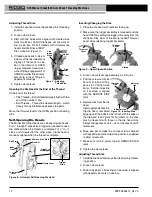
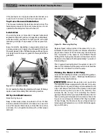
Figure 30 – Removing Chip Tray

Replace thread cutting oil when it becomes dirty or con-
taminated. To drain the oil, position a container under drain
plug at end of reservoir and remove plug. Clean build up
from  the  bottom  of  the  reservoir.  Use  RIDGID Thread
Cutting Oil for high quality threads and maximum die life.
Reservoir in the base will hold approximately 7 qt (6,6 l) of
thread cutting oil.

The oil pump should self-prime if the system is clean. If it
does not, this indicates that the pump is worn and should be
serviced. Do not attempt to prime the pump.

Priming the Model A oil Pump

Current 535 threading machines use self-priming pumps.
Machines made prior to June 1, 1996 have the Model A oil
pump and may require priming.

RIDGID  Model  535,  500  and  500A

Thread  ing Machines equipped with a Model A oil pump
should have an oil pump priming port tube extension and
a top cover access hole to allow the oil pump to be primed
without  removing  the  top  cover  of  the  machine. This
reduces  the  risk  of  injury  from  contacting  the  internal
gearing of the machine. If your pre-1996 machine does not
have a priming port tube extension and access hole in the
top  cover,  we  strongly  recommend  that  they  be  added.
Contact  Ridge Tool Technical  Service  Department  at
[email protected], or (800) 519-3456 regard-
ing a retrofit policy.

If the jaw inserts do not grip and need to be cleaned, use
a wire brush to remove any build up of pipe scale, etc.

Top Cover Removal/Installation

The top cover is retained by fasteners at each corner. The
fasteners are secured to the cover to prevent loss. Do not
operate the threading machine with cover off.

Lubrication

On a monthly basis (or more often if needed) lubricate all
exposed moving parts (such as carriage rails, cutter wheels,
cutter feed screw, jaw inserts and pivot points) with a light
lubricating oil. Wipe off any excess oil from exposed sur-
faces.

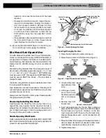
Every 2-6 months, depending on usage, remove top cover
and use grease gun to apply Lithium based EP (Extreme
Pressure) grease to the shaft bearing grease fittings 

(Figure

29)

. Apply a small amount of grease to the exposed drive

gear teeth.

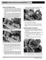
Figure 29 – Lubrication Points

Do not operate the threading machine with cover off. Always
replace cover immediately after lubricating machine.

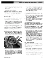
oil System Maintenance

Slide the chip tray out.

Keep  oil  filter  screen  clean  for  sufficient  oil  flow.  Oil  filter
screen is located in the bottom of oil reservoir. Loosen the
screw that secures filter to base, remove filter from oil line
and  clean.  Do  not  operate  machine  with  oil  filter  screen
removed.

WARNING

Grease

Fittings

Drive

Gear

Teeth

Oil Filter

Screen

Chip Tray

Summary of Contents for 535 Auto Chuck

Page 1: ...535 Manual Chuck 535 Auto Chuck Threading Machines Threading MachineManual 99 Washington Street Melrose MA 02176 Phone 781 665 1400 Toll Free 1 800 517 8431 Visit us at www TestEquipmentDepot com...

Page 2: ...you to potential personal injury hazards Obey all safety messages that follow this symbol to avoid possible injury or death DANGER indicates a hazardous situation which if not avoided will result in...

Page 3: ...ned from frequent use of tools allow you to become complacent and ignore tool safety principles A careless action can cause severe injury within a fraction of a second 535 Manual Chuck 535 Auto Chuck...

Page 4: ...ding Machines to reduce the risk of electrical shock or other serious injury SAVe ALL WARNINGS ANd INSTRuCTIoNS FoR FuTuRe ReFeReNCe Keep this manual with machine for use by the operator Threading Mac...

Page 5: ...l Chuck 535 Auto Chuck Threading Machines Chuck Handwheel Die Head No 820 Cutter No 341 Reamer Chip Tray REV OFF FOR 2 0 1 Switch Foot Switch Carriage Handwheel Length Gauge Die Head No 820 Cutter No...

Page 6: ...Centering Device Cam Action rotates with Chuck Automatic Centering only Die Heads See RIDGID Catalog for available Die Heads Cutter Model 820 1 8 2 Full Floating Self Centering Cutter Reamer Model 34...

Page 7: ...uipment being used per its instructions to make sure it is functioning properly 999 998 086 10_REV C 7 Selection of appropriate materials and instal lation joining and forming methods is the responsib...

Page 8: ...rts Move the REV OFF FOR 2 0 1 Switch to the FOR 1 position Press and release the foot switch Chuck should rotate counter clockwise when viewed from the carriage end see Figure 22 Repeat for REV posit...

Page 9: ...your die head Always cut a test thread to confirm proper thread size after changing adjusting the Dies Removing Installing die Head Insert remove Die Head Post into mating hole in car riage When full...

Page 10: ...ead Size 1 Install the die head move the die head into threading position 2 Loosen clamp lever 3 Start with link index mark aligned with desired size mark on size bar On Bolt die heads set link mark a...

Page 11: ...engagement or UNDER smaller thread dia meter more turns of fitting en gagement markings 5 Tighten clamp lever Trigger Slide Adjustment Position the Trigger Slide for the size of pipe being thread ed...

Page 12: ...k process and the foot switch do not operate with more than one person In case of entanglement the operator must be in control of the foot switch Follow operating instructions to reduce the risk of in...

Page 13: ...used for cutting and reaming Threading Speed Selection Up to 36 RPM Suitable for threading up to 2 pipe bolt threading high torque applications like stainless steel and high hardness material 46 RPM S...

Page 14: ...o the FOR position 4 With both hands grasp the pipe cutter feed handle 5 Depress the foot switch 6 Tighten the feed screw handle one half turn per rota tion of the pipe until the pipe is cut More aggr...

Page 15: ...verse REV with dies engaged 9 Remove foot from the foot switch 10 Move the REV OFF FOR Switch to the OFF posi tion 11 Turn the carriage handwheel to move the die head past the end of the pipe Raise th...

Page 16: ...the OFF 0 position Figure 24 LH or RH Oil Flow Selector Left hand threading requires the chuck jaws to grip the pipe during REV rotation of the machine a Make sure that the REV OFF FOR 2 0 1 switch i...

Page 17: ...If issues such as thread tearing waviness thin threads or pipe out of roundness are found the thread may not seal Refer to the Troubleshooting Chart for help in diagnosing these issues 3 Inspect the s...

Page 18: ...mend that they be added Contact Ridge Tool Technical Service Department at rtctechservices emerson com or 800 519 3456 regard ing a retrofit policy If the jaw inserts do not grip and need to be cleane...

Page 19: ...to hold pipe or rod during operation flip jaws to unused side or replace entire set of jaws 1 Loosen all three front cover mounting screws and remove the front cover Mounting screws are retained to fr...

Page 20: ...confirm that the belt is properly tensioned Tighten the 4 fasteners that hold the motor to the motor bracket optional equipment WARNING To reduce the risk of serious injury only use equip ment specif...

Page 21: ...tions on the threading oil label and Safety Data Sheet SDS Specific information about RIDGID Thread Cutting Oils including Hazard Identification First Aid Fire Fighting Accidental Release Measures Han...

Page 22: ...t tight on pipe 535A Brake assembly not properly adjusted 535A Replace dies Only use RIDGID Thread Cutting Oil Replace the RIDGID Thread Cutting Oil Clean chips dirt or other foreign material from bet...

Page 23: ...RIDGID logo are registered trademarks of Emerson Electric Co or RIDGID Inc in the U S and other countries All other trademarks belong to their respective holders 99 Washington Street Melrose MA 02176...

Reviews: