


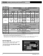


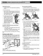


Figure 13 – Semi-Automatic Die Head
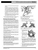
Inserting/Changing the Dies
1 Place the die head with numbers facing up.
2. Depress handle so that cam plate rests against the
change die stop
(Figure 13)
. The cam plate/handle
assembly is spring loaded and will move when de -
pressed.
3. Pull the plunger knob and rotate the handle and cam
plate counter-clockwise until it stops.
4. Remove dies from the die head.
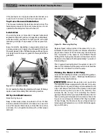
5. Insert appropriate dies into the die head, numbered
edge up until the indicator line is flush with the edge of
the diehead
(see Figure 14)
. Numbers on the dies
must correspond with
those on the die head
slots. Always change dies
as sets – do not mix dies
from different sets.
6. Rotate the handle clock-
wise so that the plunger
knob is flush against the
die head.
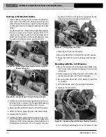
Adjusting Thread Size
1 Install the die head and move the die head into thread-
ing position.
2 Loosen the screw for the position block for desired pipe
size.
3 Start with the position block index line on the middle
size bar mark.
4 If thread size needs to be adjusted, set the index line
slightly off the mark on size bar in the direction of the
handle for larger diameter thread, (less turns of fit-
ting engagement) or away from handle for smaller
thread diameter (more turns of fitting engagement).
4. If thread size needs to be ad -
justed, set the lock screw index
line slightly off the mark on size
bar in the direction of OVER
(larger dia meter thread, less
turns of fitting engagement) or
UNDER (smaller thread dia -
meter, more turns of fitting en -
gagement) markings.
5. Tighten clamp lever.
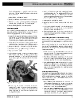
Trigger Slide Adjustment
Position the Trigger Slide for the size of pipe being thread-
ed
(see Figure 12).
•
1
/
2
" and
3
/
4
" – End of pipe should hit foot of Trigger
Slide
.
• 1" to 2" – End of pipe should hit
the shank of the Trigger Slide.
For
•
1
/
8
", ¼" and
3
/
8
" pipe
• Longer or shorter threads
• Bolt threading
Push trigger slide up and out of the
way. Die head must be opened manu-
ally.
Opening the Die Head at the End of the Thread
When using trigger it will contact the end of pipe, causing
the die head to automatically open. Stay clear of the spring
loaded Throwout Lever when it releases.
To open the die head manually (with trigger slide up), at
the end of the thread:
• Tapered Pipe Threads – End of pipe is flush with
the end of the number 1 die.
• Bolt and Straight Threads – Thread the desired
length – watch closely for any interference between
the parts.
Move the throwout lever to the OPEN position, retracting
dies.
Semi-Automatic die Heads
Semi-Automatic Die Heads include Model 816/817 NPT
(RH) die heads. The Semi-Automatic Die Heads can be
quickly adjusted from size to size and are manually opened
and closed for user specified thread length.
999-998-086.10_REV. C
11
535 Manual Chuck/535 Auto Chuck Threading Machines
Figure 11 – Adjusting
Thread Size
Lock
Screw
Index
Line
Size
Bar
“Over”
“Under”
1" thru 2"
pipe hit
this
surface
Trigger
Slide
1
/
2
" and
3
/
4
"
pipe hit this
surface
Figure 12 – Setting
the
Trigger
Plunger
Knob
Handle
Position Blocks
Change Die
Stop
Post
Front (Closed)
Back (Open)
Cam Plate
Figure 14 – Inserting Dies
Indicator Line


