RIDGID 535 Auto Chuck Manual Download Page 2

999-998-086.10_REV. C

2

535 Manual Chuck/535 Auto Chuck Threading Machines

General Power Tool Safety
Warnings*

WARNING

Read  all  safety  warnings,  instructions,  illustra-
tions and specifications provided with this power
tool. Failure to follow all instructions listed below
may  result  in  electric  shock,  fire  and/or  serious
injury.

SAVe ALL WARNINGS ANd INSTRuCTIoNS

FoR FuTuRe ReFeReNCe!

The  term  "power  tool"  in  the  warnings  refers  to  your
mains-operated (corded) power tool or battery-operated
(cordless) power tool.

Work Area Safety

Keep work area clean and well lit.

Cluttered or dark

areas invite accidents.

Do  not  operate  power  tools  in  explosive  atmo-
spheres, such as in the presence of flam mable liq-
uids, gases, or dust

.

Power tools create sparks which

may ignite the dust or fumes.

Keep children and bystanders away while operat-
ing a power tool.

Distractions can cause you to lose

control.

electrical Safety

Power  tool  plugs  must  match  the  outlet.  Never
modify the plug in any way. Do not use any adap ter
plugs  with  earthed  (grounded)  power  tools. 

Un -

modified plugs and matching outlets will reduce risk of
electric shock.

Avoid body contact with earthed or grounded sur-
faces such as pipes, radiators, ranges and refrig-
erators. 

There is an increased risk of electrical shock

if your body is earthed or grounded.

Do not expose power tools to rain or wet condi-
tions. 

Water entering a power tool will increase the risk

of electrical shock.

Do  not  abuse  the  cord.  Never  use  the  cord  for
carrying,  pulling  or  unplugging  the  power  tool.
Keep  cord  away  from  heat,  oil,  sharp  edges  or
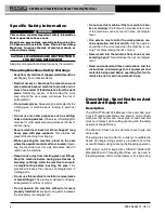
Safety Symbols

In this operator’s manual and on the product, safety symbols and signal words are used to communicate important safe-
ty information. This section is provided to improve understanding of these signal words and symbols.

This is the safety alert symbol. It is used to alert you to potential personal injury hazards. Obey all safety messages that follow this
symbol to avoid possible injury or death.

DANGER indicates a hazardous situation which, if not avoided, will result in death or serious injury.

WARNING indicates a hazardous situation which, if not avoided, could result in death or serious injury.

CAUTION indicates a hazardous situation which, if not avoided, could result in minor or moderate injury.

NOTICE indicates information that relates to the protection of property.

NOTICE

dANGeR

WARNING

CAuTIoN

* The text used in the General Power Tool Safety Warnings section of this manual is verbatim, as required, from the applicable UL/CSA 62841-1 edition standard. This

section contains general safety practices for many different types of power tools. Not every precaution applies to every tool, and some do not apply to this tool.

This symbol indicates the risk of machine tipping, caus-
ing striking or crushing injuries.

This symbol indicates the risk of fingers, legs, clothes and
other objects catching and/or wrapping on rotating shafts
causing crushing or striking injuries.

This symbol means read the operator’s manual carefully
before using the equipment to reduce the risk of injury.
The  operator’s  manual  contains  important  information

on the safe and proper operation of the equipment.

This symbol means always wear safety glasses with side
shields or goggles while using this equipment to reduce
the risk of injury.

This symbol indicates the risk of fingers, hands, clothes
and other objects catching on or between gears or other
rotating parts and causing crushing injuries.

This symbol indicates the risk of electrical shock.

This  symbol  means  do  not  disconnect  foot  switch  to
reduce the risk of injury.

This symbol means do not block foot switch (lock in ON
position) to reduce the risk of injury.

This symbol means do not wear gloves while operating
this machine to reduce the risk of entanglement.

This symbol means always use a foot switch when using
a threading machine/power drive to reduce the risk of
injury.

Summary of Contents for 535 Auto Chuck

Page 1: ...535 Manual Chuck 535 Auto Chuck Threading Machines Threading MachineManual 99 Washington Street Melrose MA 02176 Phone 781 665 1400 Toll Free 1 800 517 8431 Visit us at www TestEquipmentDepot com...

Page 2: ...you to potential personal injury hazards Obey all safety messages that follow this symbol to avoid possible injury or death DANGER indicates a hazardous situation which if not avoided will result in...

Page 3: ...ned from frequent use of tools allow you to become complacent and ignore tool safety principles A careless action can cause severe injury within a fraction of a second 535 Manual Chuck 535 Auto Chuck...

Page 4: ...ding Machines to reduce the risk of electrical shock or other serious injury SAVe ALL WARNINGS ANd INSTRuCTIoNS FoR FuTuRe ReFeReNCe Keep this manual with machine for use by the operator Threading Mac...

Page 5: ...l Chuck 535 Auto Chuck Threading Machines Chuck Handwheel Die Head No 820 Cutter No 341 Reamer Chip Tray REV OFF FOR 2 0 1 Switch Foot Switch Carriage Handwheel Length Gauge Die Head No 820 Cutter No...

Page 6: ...Centering Device Cam Action rotates with Chuck Automatic Centering only Die Heads See RIDGID Catalog for available Die Heads Cutter Model 820 1 8 2 Full Floating Self Centering Cutter Reamer Model 34...

Page 7: ...uipment being used per its instructions to make sure it is functioning properly 999 998 086 10_REV C 7 Selection of appropriate materials and instal lation joining and forming methods is the responsib...

Page 8: ...rts Move the REV OFF FOR 2 0 1 Switch to the FOR 1 position Press and release the foot switch Chuck should rotate counter clockwise when viewed from the carriage end see Figure 22 Repeat for REV posit...

Page 9: ...your die head Always cut a test thread to confirm proper thread size after changing adjusting the Dies Removing Installing die Head Insert remove Die Head Post into mating hole in car riage When full...

Page 10: ...ead Size 1 Install the die head move the die head into threading position 2 Loosen clamp lever 3 Start with link index mark aligned with desired size mark on size bar On Bolt die heads set link mark a...

Page 11: ...engagement or UNDER smaller thread dia meter more turns of fitting en gagement markings 5 Tighten clamp lever Trigger Slide Adjustment Position the Trigger Slide for the size of pipe being thread ed...

Page 12: ...k process and the foot switch do not operate with more than one person In case of entanglement the operator must be in control of the foot switch Follow operating instructions to reduce the risk of in...

Page 13: ...used for cutting and reaming Threading Speed Selection Up to 36 RPM Suitable for threading up to 2 pipe bolt threading high torque applications like stainless steel and high hardness material 46 RPM S...

Page 14: ...o the FOR position 4 With both hands grasp the pipe cutter feed handle 5 Depress the foot switch 6 Tighten the feed screw handle one half turn per rota tion of the pipe until the pipe is cut More aggr...

Page 15: ...verse REV with dies engaged 9 Remove foot from the foot switch 10 Move the REV OFF FOR Switch to the OFF posi tion 11 Turn the carriage handwheel to move the die head past the end of the pipe Raise th...

Page 16: ...the OFF 0 position Figure 24 LH or RH Oil Flow Selector Left hand threading requires the chuck jaws to grip the pipe during REV rotation of the machine a Make sure that the REV OFF FOR 2 0 1 switch i...

Page 17: ...If issues such as thread tearing waviness thin threads or pipe out of roundness are found the thread may not seal Refer to the Troubleshooting Chart for help in diagnosing these issues 3 Inspect the s...

Page 18: ...mend that they be added Contact Ridge Tool Technical Service Department at rtctechservices emerson com or 800 519 3456 regard ing a retrofit policy If the jaw inserts do not grip and need to be cleane...

Page 19: ...to hold pipe or rod during operation flip jaws to unused side or replace entire set of jaws 1 Loosen all three front cover mounting screws and remove the front cover Mounting screws are retained to fr...

Page 20: ...confirm that the belt is properly tensioned Tighten the 4 fasteners that hold the motor to the motor bracket optional equipment WARNING To reduce the risk of serious injury only use equip ment specif...

Page 21: ...tions on the threading oil label and Safety Data Sheet SDS Specific information about RIDGID Thread Cutting Oils including Hazard Identification First Aid Fire Fighting Accidental Release Measures Han...

Page 22: ...t tight on pipe 535A Brake assembly not properly adjusted 535A Replace dies Only use RIDGID Thread Cutting Oil Replace the RIDGID Thread Cutting Oil Clean chips dirt or other foreign material from bet...

Page 23: ...RIDGID logo are registered trademarks of Emerson Electric Co or RIDGID Inc in the U S and other countries All other trademarks belong to their respective holders 99 Washington Street Melrose MA 02176...

Reviews: