DRIVE UNIT
SM 3-27
G144/G145
R
ep
lac
em
en
t
Adjus
tm
ent
3.9 DRIVE UNIT
Remove the following before removing the drive assembly:
Front Cover 3.2.1
Rear Cover 3.2.3
Top Cover 3.2.4
Left and Right Side Cover 3.2.5, 3.2.6
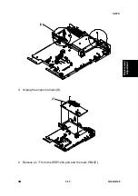
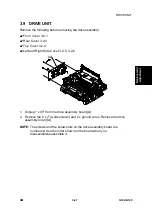
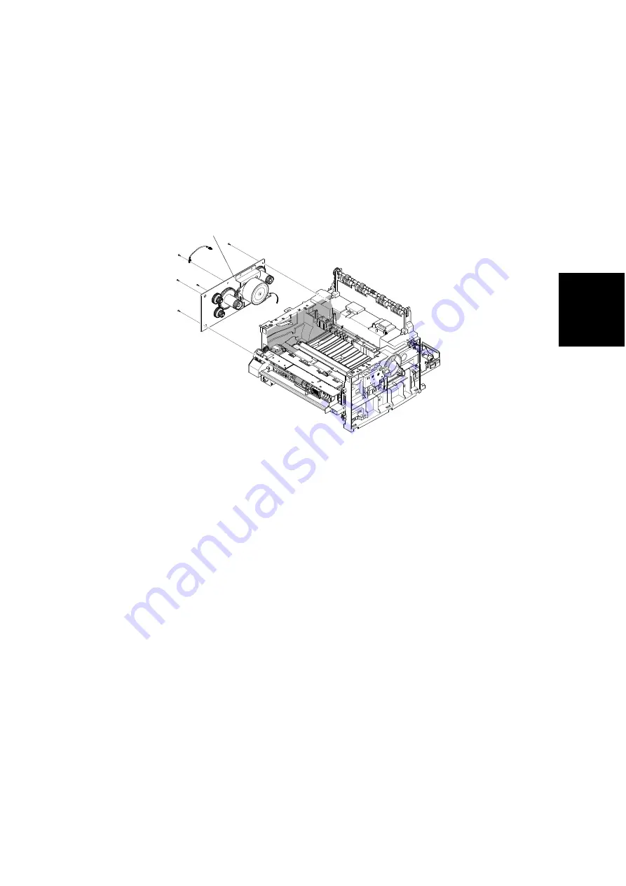
1. Unplug 1 x
from the drive assembly board [A].
2. Remove the 6 x
(white screws) and 2 x ground wires. Remove the drive
assembly board [A].
NOTE:
The screws and the screw slots on the drive assembly board are
numbered. Use the order shown on the board when you
disassemble/reassemble it.
G144R029.WMF
[A]
Summary of Contents for Aficio BP20N
Page 1: ...G144 G145 SERVICE MANUAL 002540MIU ...
Page 2: ......
Page 3: ...G144 G145 SERVICE MANUAL ...
Page 4: ......
Page 5: ...G144 G145 SERVICE MANUAL 002540MIU ...
Page 6: ......
Page 8: ......
Page 10: ......
Page 12: ......
Page 18: ......
Page 26: ......
Page 27: ...INSTALLATION ...
Page 28: ......
Page 30: ......
Page 31: ...PREVENTIVE MAINTENANCE ...
Page 32: ......
Page 34: ......
Page 35: ...REPLACEMENT AND ADJUSTMENT ...
Page 36: ......
Page 72: ......
Page 73: ...TROUBLESHOOTING ...
Page 74: ......
Page 105: ...SERVICE PROGRAM MODE ...
Page 106: ......
Page 111: ...DETAILED DESCRIPTIONS ...
Page 112: ......
Page 135: ...SPECIFICATIONS ...
Page 136: ......
Page 141: ...APPENDIX ...
Page 142: ......

