SMPS
AND
HVPS
SM 6-19
G144/G145
Detailed
Des
cription
s
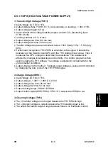
6.5.1 HVPS (HIGH VOLTAGE POWER SUPPLY)
1. Transfer High Voltage (THV+)
•
Input voltage: 24 V DC ± 15%
•
Output voltage: Max +5.0KV ± 5 %, (duty variable, no loading ). 1.2KV ±15%
•
Output voltage trigger: 6.5 uA
•
Input contrast of the voltage stability degree: under ± 5 % (fluctuating input
21.6V~26.4V)
•
Loading contrast: ± 5 % or less
•
Output voltage rise time:100 ms max
•
Output voltage fall time: 100 ms max
•
Transfer voltage range as environment varies: +650 V(duty 10%) ~ 5 KV (duty
90%)
•
Environment recognition: THV-PWM is a transfer active signal. It detects the
resistance of the transfer roller/OPC with the THV voltage (fixed value). Then it
measures the OPC voltage to determine the resistance. The resistance is
affected by changes in temperature and humidity. The control program is then
used to enable the THV voltage. The voltage is adjusted to compensate for the
environmental conditions.
•
Output voltage control method : Transfer output voltage is sourced and controlled
by changing the duty cycle of the THV PWM signal.
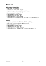
2. Charge Voltage (MHV)
•
Input voltage: 24 V DC ± 15%
•
Output voltage: -1.3KV ~-1.8KV DC ± 50V
•
Output voltage rise time: 50 ms max
•
Output voltage fall time: 50 ms max
•
Output loading range: 30 M
Ω
~1000 M
Ω
•
Output control signal (MHV-PWM): CPU = HV output when PWM is low
3. Cleaning Voltage (THV-)
•
The (+) transfer voltage is not output because the THV PWM is high.
•
The (-) transfer voltage is output because the THV-enable signal is low.
•
The output fluctuation range is large because there is no Feedback control.
Summary of Contents for Aficio BP20N
Page 1: ...G144 G145 SERVICE MANUAL 002540MIU ...
Page 2: ......
Page 3: ...G144 G145 SERVICE MANUAL ...
Page 4: ......
Page 5: ...G144 G145 SERVICE MANUAL 002540MIU ...
Page 6: ......
Page 8: ......
Page 10: ......
Page 12: ......
Page 18: ......
Page 26: ......
Page 27: ...INSTALLATION ...
Page 28: ......
Page 30: ......
Page 31: ...PREVENTIVE MAINTENANCE ...
Page 32: ......
Page 34: ......
Page 35: ...REPLACEMENT AND ADJUSTMENT ...
Page 36: ......
Page 72: ......
Page 73: ...TROUBLESHOOTING ...
Page 74: ......
Page 105: ...SERVICE PROGRAM MODE ...
Page 106: ......
Page 111: ...DETAILED DESCRIPTIONS ...
Page 112: ......
Page 135: ...SPECIFICATIONS ...
Page 136: ......
Page 141: ...APPENDIX ...
Page 142: ......

