background image

4

5

PRE-INSTALLATION ASSEMBLY REQUIREMENTS

BEFORE INSTALLATION, ENSURE THAT YOUR DOOR IS PROPERLY BALANCED AND RUNNING 

SMOOTHLY. ALSO ENSURE THAT THE LIMIT BRACKETS (SUPPLIED) ARE INSTALLED AND  

SECURED PROPERLY. BUMPER/PUSHER SPRINGS MAY BE USED IN PLACE OF, OR IN ADDITION TO 

LIMIT BRACKETS FOR DYNA-HOIST OPERATORS, BUT MUST BE INSTALLED PRIOR TO OPERATION.

Operator Mounting Requirements

Dyna-Hoist operators are mounted directly on the door shaft. Before installing the operator, please ensure follow-

ing criteria is met:

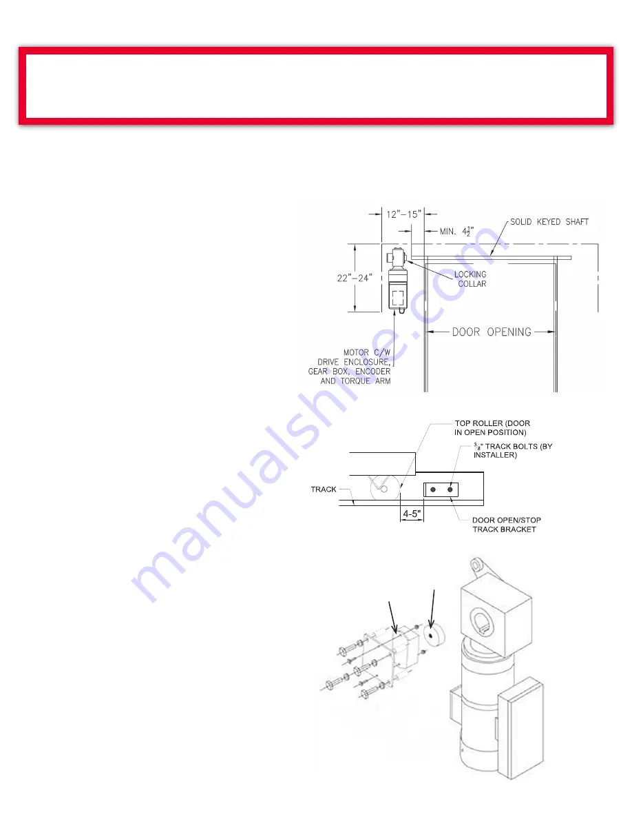
The door is well balanced, is tested for smooth 

functioning without any unusual noise.

Provided Limit Brackets must be installed 

4"-5" past door's desired open position (and within 

allowable maximum cable height) to prevent the 

doors from over-travel. (See Fig. 1A)

The door has a solid keyed shaft with a minimum 

exposed length of 4.5” on the operator side.

Clearance of at least 12” horizontally from the 

side of the door (or 9” from end of shaft), and 

24” vertically below the shaft. There is adequate 

structural support surface to securely install the 

torque arm mounting bracket, the torque arm and 

the junction box. For more details, see mounting 

installation instructions

Fig: 1 & 7.

Mounting space for the operator Control Panel 

(Min. 5 ft. from ground level, within clear sight of the 

door but far enough away as to prevent users from 

contacting moving parts).

Left Hand Mounting:

The factory default mounting as shown 

(Shown in Fig: 2) is for left-hand side of the 

door, hence no modification is required.

FIGURE: 1

FIGURE: 2

Magnet on 

this side

Encoder

FIGURE: 1A

Summary of Contents for DYNA-HOIST DC Series

Page 1: ...Installation Manual and Setup User Instructions FOR USE ONLY WITH PROPERLY BALANCED SECTIONAL DOORS AND ROLLING STEEL Dyna Hoist DC Installation Manual and Setup User Instructions R0 Engineered for L www rwdoors ca dynahoist DYNA HOIST DC SERIES ...

Page 2: ...PWM Frequency Page 21 Set Dynamic Brake Page 21 Set Opening Force Page 21 Set Closing Force Page 21 Set Open Slow Speed Page 22 Set Close Slow Speed Page 22 Set Open Rampdown Distance Page 22 Set Close Rampdown Distance Page 22 Set Open Limit Options Push Button Remote Page 22 Set Output Relay Page 22 Set Calibration Page 23 Set Maintenance Schedule Page 23 Set Red Flashing Page 23 Set Advanced Re...

Page 3: ... Hoist Operator will initiate Push Hold to CLOSE protocols should devices in Terminal 1 and 2 be found non functional misaligned or unconnected at least one functional device must be connected and verified in either Terminal 1 or Terminal 2 Note that during Push Hold to Close protocols the door will reverse should it not fully reach the closed limit per UL 325 BOX INVENTORY Before beginning instal...

Page 4: ...local codes must be followed 1 READ AND FOLLOW ALL INSTALLATION INSTRUCTIONS 2 Have qualified service personnel make necessary repairs to ensure door is operating smoothly without any unusual noise Install operator only on a smoothly operating and well balanced door 3 Remove all pull ropes and remove locks unless mechanically and or electrically interlocked to the power unit connected to the door ...

Page 5: ...ition and within allowable maximum cable height to prevent the doors from over travel See Fig 1A The door has a solid keyed shaft with a minimum exposed length of 4 5 on the operator side Clearance of at least 12 horizontally from the side of the door or 9 from end of shaft and 24 vertically below the shaft There is adequate structural support surface to securely install the torque arm mounting br...

Page 6: ...ENSURE THAT THE MAGNET IS VISIBLE AND FACING OUTWARDS FIG 3 PRIOR TO INSERTION Attach the encoder mounting plate to right side of the gearbox so that it covers the encoder magnet assembly ensuring that the cable is facing towards the bottom of the operator use existing bolts and spacers Ensure that bolts are fully tightened DO NOT TWIST THE CABLE Please note that the face of the encoder should not...

Page 7: ...7 TORQUE ARM POSITION IN RELATION TO OPERATOR ...

Page 8: ...TORY PRIOR TO OPERATOR INSTALLATION WITHOUT PHYSICAL LIMITS THE DOOR CAN RUN OUT OF ITS TRACKS AND CAUSE SEVERE PERSONAL INJURY AND OR CAUSE SEVERE DAMAGE TO THE DOOR FURTHERMORE YOU WILL BE UNABLE TO SET THE LIMITS MOUNTING INSTALLATION INSTRUCTION Shaft Collar Key Installation The Shaft Collar serves as an end stop for the gearbox on the shaft to prevent possible damage to the encoder magnet It ...

Page 9: ...r provided NOTE DO NOT TIGHTEN THE NUT FULLY Anchor the Torque Arm Bracket to the solid structural support Fasten the torque arm to structural support by means of the supplied bolt locking nut and washers The supplied bracket may be required If the torque arm does not align with structural support you may try adjusting the torque arm position on the gearbox see Assembling Torque Arm to Gearbox acc...

Page 10: ...6 inches from the ground The sensor reflective photo eye or receiver thru beam should be mounted on the operator side as it will be wired into the control panel while the reflector or transmitter should be mounted on the opposite side of the door facing the sensor receiver so that its center meets the beam Use the included mounting bracket s to secure to either the door tracks or the wall Refer to...

Page 11: ...NOTE 14AWG is recommended for Dyna Hoist 1000 Operators 2 These wires should be run together with the Control Panel Connections through the bottom of the enclosure and connect to the and DRIVE terminals on the board 3 Place the batteries into the Control Panel Connect the wires to the batteries as labeled fused lead connects to the Positive Red contact blue lead to the Negative Black contact Fully...

Page 12: ...on details Push Button Stations are available from RW please contact us for details Remote Radio Connect your receiver to the provided terminals as the Dyna Hoist control panel enclosure is non metallic external antenna not necessarily required Note that Remote Radio can be programmed to raise the door to the fully open or set limit position Refer to the wiring diagram for further connection detai...

Page 13: ...13 WIRING DIAGRAMS ...

Page 14: ...14 ...

Page 15: ...15 ...

Page 16: ...16 ...

Page 17: ...17 ...

Page 18: ... the screen Once accomplished you can scroll between the various QUICKSTART MENU options by pressing the OPEN and CLOSE buttons Once you have reached a selection that you would like to alter press the STOP button Use the OPEN and CLOSE buttons to scroll toggle between options within the selection and then press STOP to save your selection and return to the QUICKSTART MENU CLOSING TIMER IT IS NOT R...

Page 19: ... and the door will open to the fully open position against the Limit Brackets ENSURE THAT THE TOP ROLLERS OF THE DOOR ARE RESTING AGAINST THE LIMIT BRACKETS The Open Limit now needs to be set SET OPEN LIMIT Press CLOSE OPEN functional should you overshoot desired position to jog the door to the desired Open Limit height The Open Limit Setting Should be a minimum offset of 3 from the Limit Bracket ...

Page 20: ... door using the OPEN and CLOSE buttons During Jog Mode all limits are de activated and push hold protocols are initiated This selection can be used to test door functionality without the encoder ensure proper door balance or as a method to operate the door under power should the encoder malfunction The door will travel in each direction at the set OPEN SLOW SPEED and CLOSE SLOW SPEED see Page 22 f...

Page 21: ...require dynamic braking compensation Factory default is for no Dynamic Braking OFF and is recommended for standard operation Should Dynamic Braking prove necessary press the OPEN CLOSE buttons to toggle between choices Low Medium High Note that the addition of Dynamic Braking is intended to assist doors with high inertia in achievement of a soft stop It is recommend that before setting Dynamic Bra...

Page 22: ...auto which is configured by the system or the desired number of shaft rotations between 0 5 turns and 3 turns in half rotation increments The Factory setting for this feature is AUTO This should not be changed unless recommended by Dyna Hoist Technical Support CLOSE RAMPDOWN DISTANCE This setting is used to change the point where the door begins to decelerate to slow speed as it approaches the Clo...

Page 23: ...ress the OPEN or CLOSE buttons to change and Press and Hold the buttons for rapid scrolling to your required cycle setting RED FLASHING Set this feature to ON if you prefer the red light of an attached LED Stop Go Light to flash while the door is in motion ADVANCED RED Used in conjuction with the CLOSING TIMER Page 18 this safety feature turns on the red light or flashing red light if this setting...

Page 24: ... 250 000 Cycles Open Limit Switch No Close Ramp Up Time 1 0 Seconds Motion Detect Time 0 3 Seconds After performing factory reset if deemed necessary adjust settings as required and re program limit settings and perform calibration thereafter EXITING ADVANCED MENU CALIBRATION TESTING To exit from the ADVANCED MENU press and release the STOP button while ADVANCED MENU appears on the LCD This will b...

Page 25: ...ovides a monitored trickle charger in order to maintain the batteries life Should the batteries be fully drained and no longer accept a charge please replace them with equivalent batteries and dispose of the expired units according to local environmental regulations NEVER remove the provided jumper between the batteries unless in the process of replacement and be sure to re connect in the event ba...

Page 26: ...26 DYNA HOIST OPERATOR COMPONENTS ...

Page 27: ...AT RANDOM DOES NOT RECOGNIZE LIMITS POSITION ENCODER WORN IMPROPERLY INSTALLED OR HAS MOVED Check encoder for wear re position if necessary It is critical that the set collar on the shaft be set at 3 from the end Run limits setup replace encoder if problem persist DOOR CONSTANTLY STOPS SHORT OF CLOSE POSITION MOTOR POSITION SETTING MAY BE INCORRECT Check Motor Position from SETUP menu Operator pos...

Page 28: ...install the jumper THE REMOTE PUSH BUTTON DOES NOT HAVE THE NC NORMALLY CLOSED CONTACT FOR THE STOP BUTTON Replace the push button station or the contact for the STOP button for one that has an NC contact on the STOP button REMOTE PUSH BUTTON STATION WIRED INCORRECTLY Check and correct wiring as necessary DOOR DOES NOT CLOSE ON REMOTE OR CLOSE TIMER PUSHER SPRINGS MAY BE PREVENTING DOOR TO OPEN FU...

Page 29: ...stM BRUSH Gearbox GB 50 1 0 GB 50 1 0 GB 75 1 25 Drive Controls Enclosure PDyna Hoist ENC ALBK PDyna Hoist ENC ALBK PDyna Hoist ENC ALBK Drive Replacement Board PCB PDyna HoistDRIVE3 PCB PDyna HoistDRIVE3 PCB PDyna HoistDRIVE3 Torque Arm TQARM 50 TQARM 50 TQARM 75 Torque Arm Bracket TQBKT 50 TQBKT 50 TQBKT 75 Limit Stop Brackets w Hardware PDyna Hoist LMTBKT PDyna Hoist LMTBKT PDyna Hoist LMTBKT S...

Page 30: ...e field assistance additional fees may apply and or advice with installation troubleshooting product enhancement or improvement of our product Under the terms of this limited warranty for any door components that are found to be defective upon inspection by authorized Richards Wilcox personnel Richards Wilcox will replace the defective door components Labour charges for installation or repairs sha...

Page 31: ...31 NOTES ...

Page 32: ... 5100 Timberlea Boulevard Mississauga Ontario Canada L4W 2S5 Toll Free 1 800 667 1572 Dyna Hoist Technical Support 1 833 785 7332 Tel 905 625 0037 Fax 905 625 0057 Email info rwdoors com www rwdoors com dynahoist DYNA HOIST DC SERIES ...

Reviews: