


32
iQUBE
Installation Manual
calibration.
NOTE:
Cal-Match calibration can
be canceled by pressing the
CLE
A
R
key.
6. Ensure scale is empty, then use the
up
and
down
keys to select
Corner Cal-Match
(see
Figure 5-2
)
or
S
ection Cal-Match
. Press
enter
.
The
iQUBE
calculates the zero reference
point.
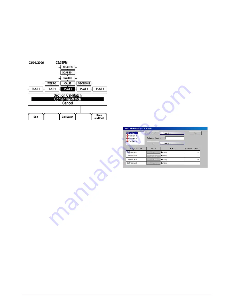
Figure 5-2.
920i
Cal-Match Selection
7. The display now prompts
Cal-Match Point 1
.
Place a test weight over the cell or section to
be tested, then press
enter
.
NOTE:
It is not
n e c e s s a r y t o m e a s u r e t h e c e l l s i n a n y
particular order.
8. Once the
iQUBE
has read the cell, the
920i
display will show
Cal-Match Point 2
. Move the
test weight to the next cell or section and
press
enter
. Repeat until all cells have been
measured.
9. When the last cell has been measured, the
iQUBE
automatically sets the load cell trim
factors. The
920i
display shows
Calibration
Complete
.
10. Press
up
to return to the SCALES menu, or
press the
S
ave and Exit
softkey to exit setup
mode.
NOTE:
Cal-Match calibration can be performed using
a vehicle as the test weight, but a smaller footprint and
heavier weight value will yield better results.
Mechanical characteristics of the scale may prevent
Cal-Match from automatically computing load cell
trim factors.
5.1.3
Manual Trim Factor Adjustment (Tweaking)
Section or corner trim factors can be manually
tweaked. When using the
iQUBE
with a
920i
indicator,
use the
up
or
down
navigation key to select the section
or corner to be adjusted, then use the
Tweak –
or
Tweak
+
softkey to adjust the value. The displayed weight for
the scale system is shown at the bottom of the weight
column.
Tweaking can be performed following a Cal-Match
calibration or when replacing a load cell.
5.1.4
Final Calibration
The span and linear calibration displays provide a
Calibration
softkey to perform a traditional calibration
for the selected point. Enter the weight value under
WVAL, then press the
Calibration
softkey under
WSPAN for each platform. Continue under WLIN for
systems using linear calibration.
Trim factors displayed for sections or corners can be
manually tweaked up or down. The cell with the
lowest output is given a trim factor of 1.0000.
5.2
Revolution III Calibration
Cal-Match Calibration
With the
iQUBE
connected to a PC running the
Revolution III
program, do the following:
1. From the Interactive menu, select
Cal-Match
Load Cell Matching…
(see Figure 5-3).
Figure 5-3. Cal-Match Load Cell Matching Display
2. Remove all weight from the scale platform.
Click on
No Load
. The word
Transmitting
is
displayed while the no-load values are
calculated. This process can last up to 45
seconds.
3. Enter the test weight value in the
Calibration
Weight
field. You are now ready to measure
the load cell outputs using the Cal-Match
procedure.
4. Place the test weight over the cell to be
measured. It is not necessary to measure the
cells in any particular order.
5. Click the first
Measure
box. As each cell is
completed the next cell becomes available for
measurement.
6. Repeat steps 4 and 5 until all cells have been
measured.
7. Click
Finish
. Cal-Match automatically
calculates the load cell trim factors. These
normalized sensitivity values are displayed
for each cell in the platform.
8. Click
Exit
.


