34
• With motor held to above position and motor lead plugs oriented to the original posi-
tion (the wire connectors on the motor must point straight to the front of the unit.
Securely tighten the bolt on the mount band to the motor shell.
• Turn the motor shaft so that the flat on the shaft is located under blower wheel
setscrew, and the blower wheel is centered in the blower housing with the same dis-
tance on each side between the inlet venturi and the outside of the blower wheel.
• Re-assemble the motor wiring (high and low voltage plugs) into the motor.
IMPORTANT: DO NOT FORCE POWER PLUG INTO THE MOTOR CONNECTOR
BACKWARDS. The A.C. power plug to the motor has locking tabs. It has been
proven that by applying excessive force to the A.C. cable half of the connector it is
possible to force the connector in backwards. It will not seat and “click” properly but
will make connection. If A.C. power is applied with the connector reversed the motor
will be immediately destroyed.
13.8 ECM CONTROL MODULE REPLACEMENT
The control module on air handlers equipped with Comfort Control
2
System™ is field
serviceable.
13.9 BLOWER WHEEL REPLACEMENT
With the blower assembly removed and the motor assembly removed (see above
instructions), remove the two screws holding the blower wrap (cutoff) to the blower
sides.
IMPORTANT: It is not necessary to remove heating ele ment(s), if provided, to remove
the blower wheel.
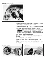
FIGURE 24
INTERNAL MOTOR PLUG AND SOCKET
FIGURE 25
ECM MOTOR COMPONENTS
FIGURE 26
MOTOR ALIGNMENT PIN
Summary of Contents for RHPL-HM2421JC
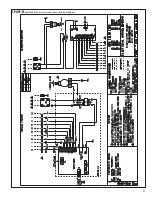
Page 37: ...37 FIGURE 29 AIR HANDLER EQUIPPED WITH Serial Communication WIRING DIAGRAM...
Page 38: ...38...
Page 39: ...39...
Page 40: ...40 CM 0411...


