


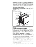


• Rotate unit into the downflow position, with the coil compartment on top and the blower com-
partment on bottom.
• A second set of coil rails must be field installed for vertical down-flow and horizontal
right applications. Fastener clearance holes will need to be drilled in the cabinet sides
(proper hole locations are marked with “dimples” for this purpose). Note that the shorter
(no notch) coil rail must be mounted on the left-hand side to provide clearance for the
drain-pan condensate connection boss.
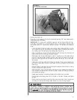
• Reinstall the indoor coil 180° from original position. Ensure the retaining channel is fully
engaged with the coil rail. (See Figure 5, Detail A.)
• Secondary drain pan kits RXBM- are required when the unit is configured for the hori-
zontal right position over a finished ceiling and/or living space. (See Section 15.0:
Accessories - Kits - Parts.)
IMPORTANT: Units cannot be installed horizontally laying on or suspended from the
back of the unit.
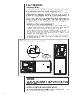
3.4 INSTALLATION IN AN UNCONDITIONED SPACE
The exterior cabinet of an air handler has a greater risk of sweating when installed in an
unconditioned space than when it is installed in the conditioned space. This is primarily
due to the temperature of the conditioned air moving through the air handler and the air
circulating around the unit where it is installed. For this reason, we recommend the fol-
lowing for all air handler applications, but special attention should be paid to those
installed in unconditioned spaces:
• Duct sizing and airflow are critical and based on the equipment selected
• Supply and return duct attachment: If other than the factory flanges are used, the
attachment of ducting must be insulated and tight to prevent sweating.
• No perimeter supply flanges are provided. If a full perimeter supply duct is used, it is
the responsibility of the installer to provide duct flanges as needed, to secure and seal
the supply duct to prevent air leakage and the sweating that will result.
• All wire penetrations should be sealed. Take care not to damage, remove or com-
press insulation in those cases.
• In some cases, the entire air handler can be wrapped with insulation. This can be
done as long as the unit is completely enclosed in insulation, sealed and service
access is provided to prevent accumulation of moisture inside the insulation.
• As required, use a secondary pan that will protect the structure from excessive sweat-
ing or a restricted coil drain line.
• If a heater kit is installed, be sure the breaker or disconnect cover is sealed tightly to
the door panel.
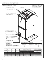
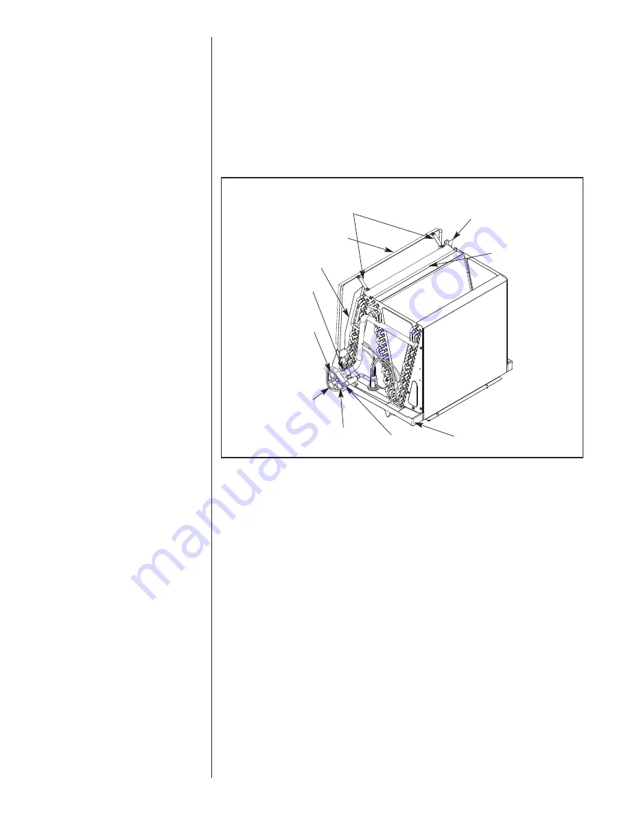
FIGURE 7
INDOOR COIL AND DRAIN PAN SET-UP
12
A-1037-01
HORIZONTAL ADAPTER
KIT
REAR WATER CATCHER
TOP AIR STOP
STRAPS
VAPOR LINE
CONNECTION
FRONT WATER
CATCHER
PRIMARY
DRAIN
CONNECTION
LIQUID LINE
CONNECTION
VERTICAL
DRAIN PAN
AUXILIARY
HORIZONTAL
DRAIN
CONNECTION
AUXILIARY
UPFLOW/DOWNFLOW
DRAIN CONNECTION
Summary of Contents for RHPL-HM2421JC
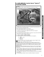
Page 37: ...37 FIGURE 29 AIR HANDLER EQUIPPED WITH Serial Communication WIRING DIAGRAM...
Page 38: ...38...
Page 39: ...39...
Page 40: ...40 CM 0411...


