16
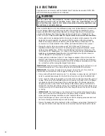
• Do not leave excess field control wiring inside unit, pull excess control wire to outside
of unit and provide strain relief for field wiring on inside of cabinet at point wiring pene-
trates cabinet.
• Make sure, after installation, separation of control wiring and power wiring has been
maintained.
5.2
Comfort Control
2
System™
CONTROL BOARD
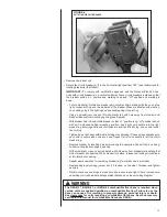
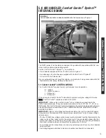
The RHPL series air handler control, Figure 8, has the following features:
• Memory Card – The memory card stores all information needed for unit operation.
Once the system is wired for serial communications, this information is shared with the
thermostat and outdoor unit. This shared data is available if one of the components in
the system needs to be replaced.
• An automotive-style ATC blade fuse for transformer protection (3 amp).
• An on-board LED to indicate blower CFM.
• An RJ-11 port for use with a diagnostic tool.
• Inputs for field installed supply and return air temperature sensors (available in kit
RXHT-A01)
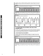
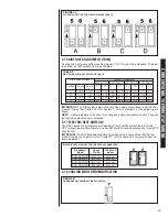
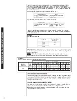
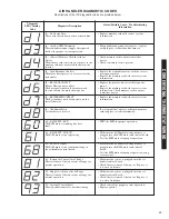
• DIP switches for airflow adjustments
IMPORTANT: The DIP switches are NOT used when the air handler is wired for serial
communications. Airflow adjustments are performed via the thermostat or a diagnostic
tool.
Installation Verification
• Term and bias dip switches should be on.
• 24V AC power on R&C must be present at the control for the air handler to operate,
reference Figure 9.
• Line voltage must be present at the control for indoor blower operation.
• The RX Data LED will flash green in normal operation. A flashing green light indicates
24VAC is present and the data wires 1 and 2 are wired properly.
IMPORTANT: Diagnostic port is for the diagnostic tool only. Do not attempt to connect
components using a telephone cord. Damage will occur.
IMPORTANT: Diagnostic port is not a phone jack. Connecting to a telephone or tele-
phone system will result in damage.
5.3 USING THE ON-BOARD LED TO DETERMINE BLOWER CFM
The CFM LED indicates blower output by flashing one (1) flash for every 100 CFM of
airflow. The LED will pause 1/10 second between each flash.
5.4 AIRFLOW ADJUSTMENTS WITH THE
Comfort Control
2
System™
The RHPL air handler Comfort Control
2
System™ may operate using the Comfort
Control
2
or via traditional thermostat wiring. When the air handler is wired for the
Comfort Control
2
using Data wire 1 and Data wire 2, the DIP switches on the Comfort
Control
2
control have NO affect on the airflow.
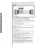
FIGURE 9
TYPICAL The Comfort Control
2
System™ WIRING DIAGRAM
Indoor Unit
1
2
C
R
WIRING INFORMATION
Line Voltage
–Field Installed - - - - - -
–Factory Standard
1
2
R
C
1
2
R
C
Communicating Thermostat
Outdoor Unit
Comfort Control
2
System™
CONTROL WIRING
Summary of Contents for RHPL-HM2421JC
Page 37: ...37 FIGURE 29 AIR HANDLER EQUIPPED WITH Serial Communication WIRING DIAGRAM...
Page 38: ...38...
Page 39: ...39...
Page 40: ...40 CM 0411...

