HN-1010/1510
LED Status
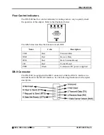
Four LED indicators are included on the front panel to provide the status of the HN-
1510 Indoor Base/Remote station. See the illustration below. These built-in flow
control indicators allow you to quickly check the operational status.
The table below describes the function of each LED.
Name Color
Description
PWR
Green
Continuous DC power is applied
TX
Red
RS-232 signal input
RX
Red
RS-232 signal output
CD
Red
Normal operation is asserted
Power Connection
The HN-1510 is supplied with a 110/ 220 wall mount power supply. However, you
can operate the HN-1510 from any well-filtered 7.5 to 24 VDC power source. The
power supply should be capable of providing 500 milliamperes of current.
The indoor base station uses a separate 2-pin power connector that accepts
7.5 to 24 VDC. Power connects to the 2-pin connector on the front panel of the
transceiver. A polyfuse is on the transceiver board to protect against short circuits.
Antenna Connection
The RF signal is brought in on a standard female TNC jack connector located on the
front panel.
Use the following guidelines when installing the antenna:
•
Strictly follow the antenna manufacturer’s installation instructions for proper
operation of the antenna.
•
Be sure to use proper polarization for any system using a gain type antenna. If you
orient the antenna with the wrong polarization, a signal reduction of greater than 20
dB could result.
•
Use a low-loss feedline with the HN-1510. Keep the feedline as short as possible to
minimize signal loss.
•
Use proper care when installing the feedline to prevent damage. Do not twist,
stretch, or kink the cable.
•
Be sure to securely fasten the cable and only use connectors that have been
recommended by the cable manufacturer.
©
2000- 2004 Cirronet
™
Inc
11
M-2410-0010 Rev A


