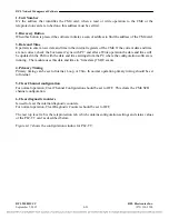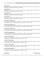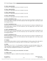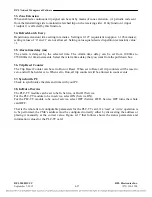
Configuration
5.2
MODULE PLACEMENT AND CABLING
5.2.1
MODULE PLACEMENT, DIGITAL CHASSIS
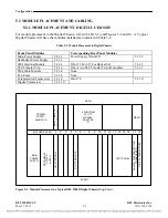
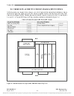
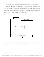
For module placement in the Digital Chassis, refer to Table 5-2, and Figures 5-2 and 8-1. A Typical
Digital Chassis will have the modules installed as indicated in Table 5-2.
Table 5-2. Module Placement in Digital Chassis
Front Panel Modules
Corresponding Rear Panel Modules
Main Power Supply
5.2.1.1
Redundant Power Supply
5.2.1.2
Power Supply Alarm I/O
5.2.1.3
CM4 Optional Module
5.2.1.4
MA-271, MA-278 or Optical I/O
5.2.1.5
PLC Transfer Trip
5.2.1.6
One or two PLC Transfer Trip I/O modules
5.2.1.7
CM4 Main Module
5.2.1.4
None
Test Panel
5.2.1.8
None
Teleprotection Transceiver
5.2.1.9
Digital Transceiver
5.2.1.10
MA-470 5.2.1.11
1
2
3
4
5
6
7
8
9
10 11 12 13 14 15 16
17 18
MAIN
POWER
SUPPLY
REDUNDANT
PO
WER
SUPPLY
POWER
SUPPLY
ALARM I/O
4-FUNCTION
PLC-TT
MODULE
ADAPTER
"A"
CM
-4 OP
TIONA
L
PLC-TT MODULE
MA-271, MA-278
OR OP
TICA
L I/O
TEST PANEL
DIG
ITAL TRANSCEIVER
MA-470
FRONT
REAR
MOTHER BOARD
ANALO
G
TELEPRO
T
ECTIO
N
TRANSCEIVER
Figure 5-2. Module Placement in a Typical RFL 9508D Digital Chassis (Top View)
RFL 9508D UCC
RFL Electronics Inc.
May 27, 2011
5-3
(973) 334-3100


